Chapter 5
MSC800
8011540/14B8/2019-06-06 Operating instructions | SICK 53
Subject to change without notice
5.3.2 Electrical connections on the MSC800-0000 logic unit (overview)
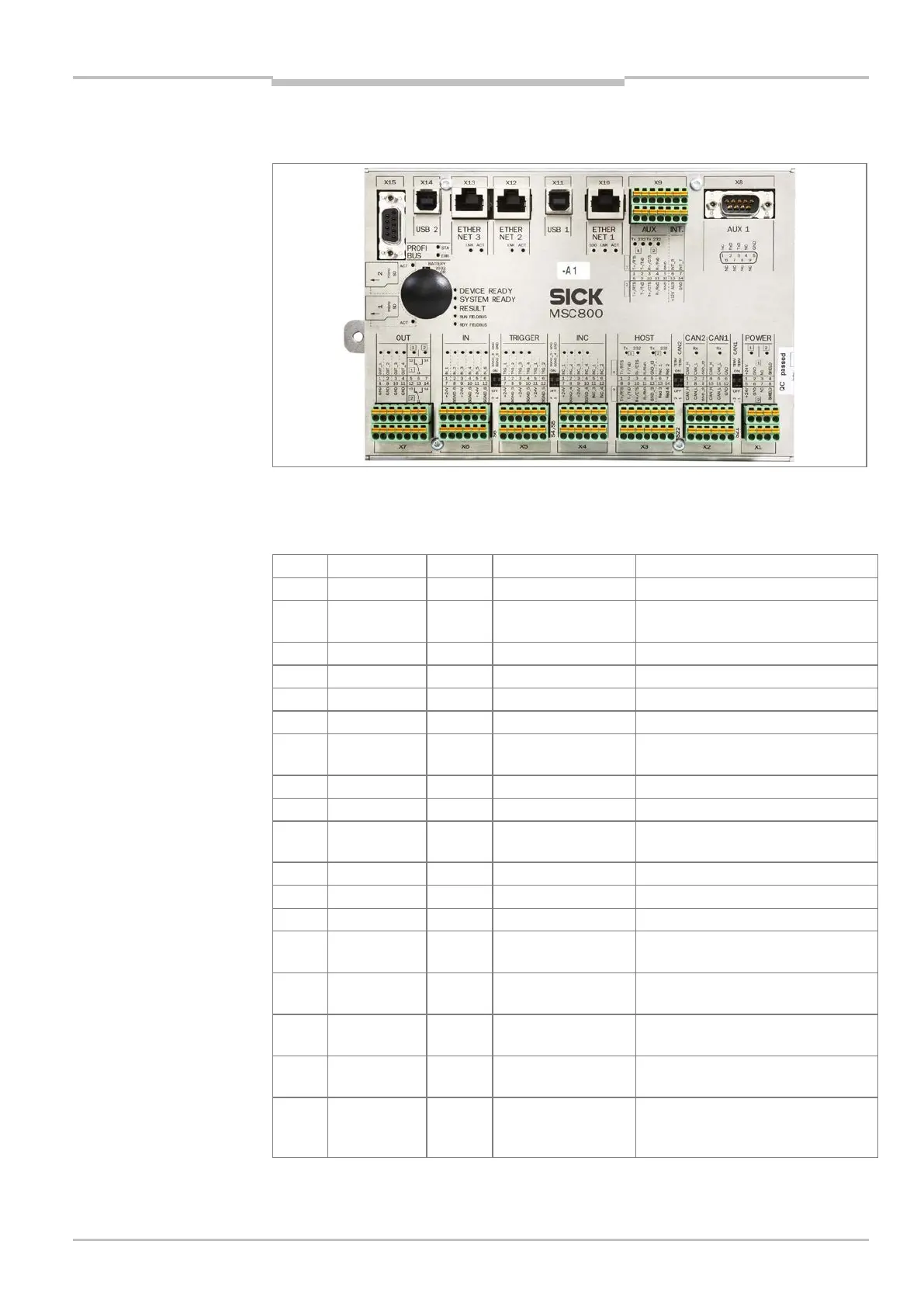
Fig. 22: MSC800-0000 logic unit in the cabinet of the MSC800-1100/-2100/-2300: position of the
electrical connections
The following interfaces are carried via the logic unit connections:
X15 PROFIBUS D-Sub 9, female connector Main data interface
X14 USB 2 USB 4, female connector Auxiliary data interface
(only for SICK service)
X11 USB 1 USB 4, female connector Auxiliary data interface
X10 ETHERNET 1 RJ-45 8, female connector Main data interface
X9 AUX (1/2) Block 10, terminals Auxiliary data interface
X8 AUX 1 D-Sub 9, male connector Auxiliary data interface (RS-232)
X7 OUT Block 8, terminals 4 digital switching outputs
(system status)
2 relay outputs (system status)
6 digital switching inputs
X5 TRIGGER Block 12, terminals 4 digital switching inputs (read cycle)
X4 INC Block 12, terminals 4 digital switching inputs (incremental
encoder)
X3 HOST (1/2) Block 14, terminals Main data interface (RS-232,
X2 CAN 2 Block 6, terminals Input/output CAN SENSOR
X2 CAN 1 Block 6, terminals Input/output CAN SENSOR
network 1
X1 POWER (1/2) Block 8, terminals Input supply voltage
DC 24 V (from the power supply unit
module)
Tab. 27 MSC800-0000: function of the electrical connections (overview)