Chapter 5
MSC800
8011540/14B8/2019-06-06 Operating instructions | SICK 61
Subject to change without notice
5.4.6 24 V DC supply voltage for the ICR890 systems
Requirements for the supply voltage
The typical power consumption of an ICR890 system is 425 W. The power required per
system is supplied in the MSC800-2300 by three power supply unit modules, in the
MSC800-3400 by two power supply unit modules, and in the MSC800-3600 by three pairs
of power supply unit modules.
The following table shows the number of ICR890 systems which can be operated per MSC800.
Variants of the MSC800 Number of ICR890 systems
MSC800-1100/-2100 –
MSC800-2300 1
Tab. 34 Number of ICR890 systems per MSC800
The wire section for the voltage supply to the ICR890 system must be at least 4 mm
2
. In
order to ensure the short-circuit/overload protection of the incoming supply cable, the
cable must be protected according to the wire sections used (as is done in the MSC800).
The following standards must be observed in this case: DIN VDE 0100 (part 430), DIN VDE
0298 (part 4), and/or DIN VDE 0981 (part 1).
Connect supply voltage for the ICR890 systems
1. Make sure that the ext. supply voltage for the MSC800 is switched off.
2. For each system, insert and fix in place the 8-pin Harting HanQ8 female connector of
the supply voltage cable no. 2032398 on the ICD890 camera in the 8-pin Harting
HanQ8 male connector POWER IN.
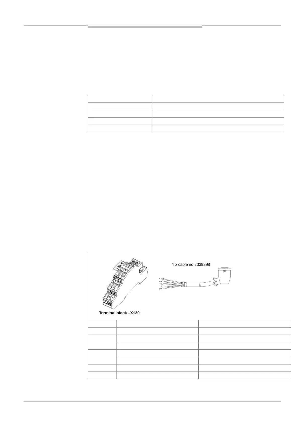
3. Lay the free cable end(s) on the terminal block for the supply voltage ICR890 (see the
following tables for each MSC800 type)
The supply voltage remains switched off for further installation work.
Wire color (numbers printed on wires)
-X120/12 GND (ICD890 camera) Wire 2: black
-X120/13 DC +24 V (ICI890_1#1 illumination) Wire 3: black
GND (ICI890_1#1 illumination)
DC +24 V (ICI890_1#2 illumination)
-X120/16 GND (ICI890_1#2 illumination) Wire 6: black
-X120/17 PE Green-yellow
Tab. 35 MSC800-2300: connection of the supply voltage cable for an ICR890 system
Important
Important