Chapter 5
MSC800
64 Operating instructions | SICK 8011540/14B8/2019-06-06
Subject to change without notice
5.4.7 DC 24 V supply voltage for CLV490 and VMS4xx/5xx
Requirements for the supply voltage
The typical power consumption of a CLV490 is 18 W. The power required for max. 14
CLV490 and one VMS4xx/5xx is supplied in the MSC800-1100/2100 by the -G1 power
supply unit module and in the MSC800-2300 by the -G2 power supply unit module.
Power is supplied via the relevant wires of the CAN cable, which are applied directly to
the terminals for the supply voltage.
Connecting supply voltage for CLV490 and VMS4xx/5xx
1. Make sure that the mains voltage (external supply voltage) for the MSC800 is switched
off.
2. Connect CAN cable to the CLV490/VMS4xx/5xx.
3. Lay the free cable ends for the supply voltage on the 12-pin terminal block for the
supply voltage CLV490 and VMS4xx/5xx of the MSC800-1100/2100 or MSC800-2300
(see chapter 5.3 Electrical connections on page 45).
5.4.8 HOST/AUX data interfaces of the logic unit
Framework conditions for the HOST and AUX data interfaces
The HOST data interface (main data interface) and the AUX data interface (auxiliary data
interface) of the MSC800 can each be operated as RS-232 or RS-422/485 design and also
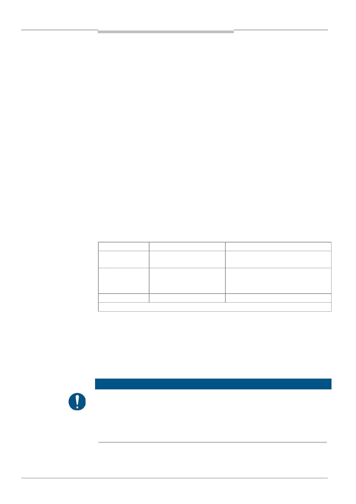
in parallel via ports on the Ethernet interface. The following table shows the recommended
maximum cable lengths depending on the interface design and the data transmission rate.
Distance to the target computer (host)
RS-232 Up to 19.2 kBd
38.4 ... 115.2 kBd
Max. 10 m
Max. 3 m
RS-422
1)
Max. 38.4 kBd
Max. 57.6 kBd
Max. 115.2 kBd
Max. 1,200 m
Max. 500 m
Max. 10 m
1) With the corresponding cable termination as per specification
Tab. 38 Maximum lengths of cable between MSC800 and Host
Use shielded data cables (twisted pair wires).
To prevent interference factors, do not lay data cables over a longer route in parallel
with power supply cables and motor cables, e.g., in cable channels.
Wiring HOST/AUX data interface of the logic unit
Damage to the interface modules!
If the HOST/AUX data interface modules are wired incorrectly, then electronic components
in the MSC800 could get damaged.
Wire data interfaces correctly (see figure below).
Carefully check the wiring prior to switching on the MSC800.
Recommendation