Chapter 5
MSC800
8011540/14B8/2019-06-06 Operating instructions | SICK 57
Subject to change without notice
5.4.1 Wire cross-sections
Wire all connections provided by the customer using shielded copper conductors.
Observe the wire cross-sections required:
• Switching inputs/outputs: at least 0.25 mm
2
• Data interfaces: at least 0.22 mm
2
• Supply voltage: the cable to the MSC800 must be at least 2.5 m from a wire section of
4 mm
2
.
Lay all of the cables such that there is no risk of people tripping over them and the
cables are protected against damage.
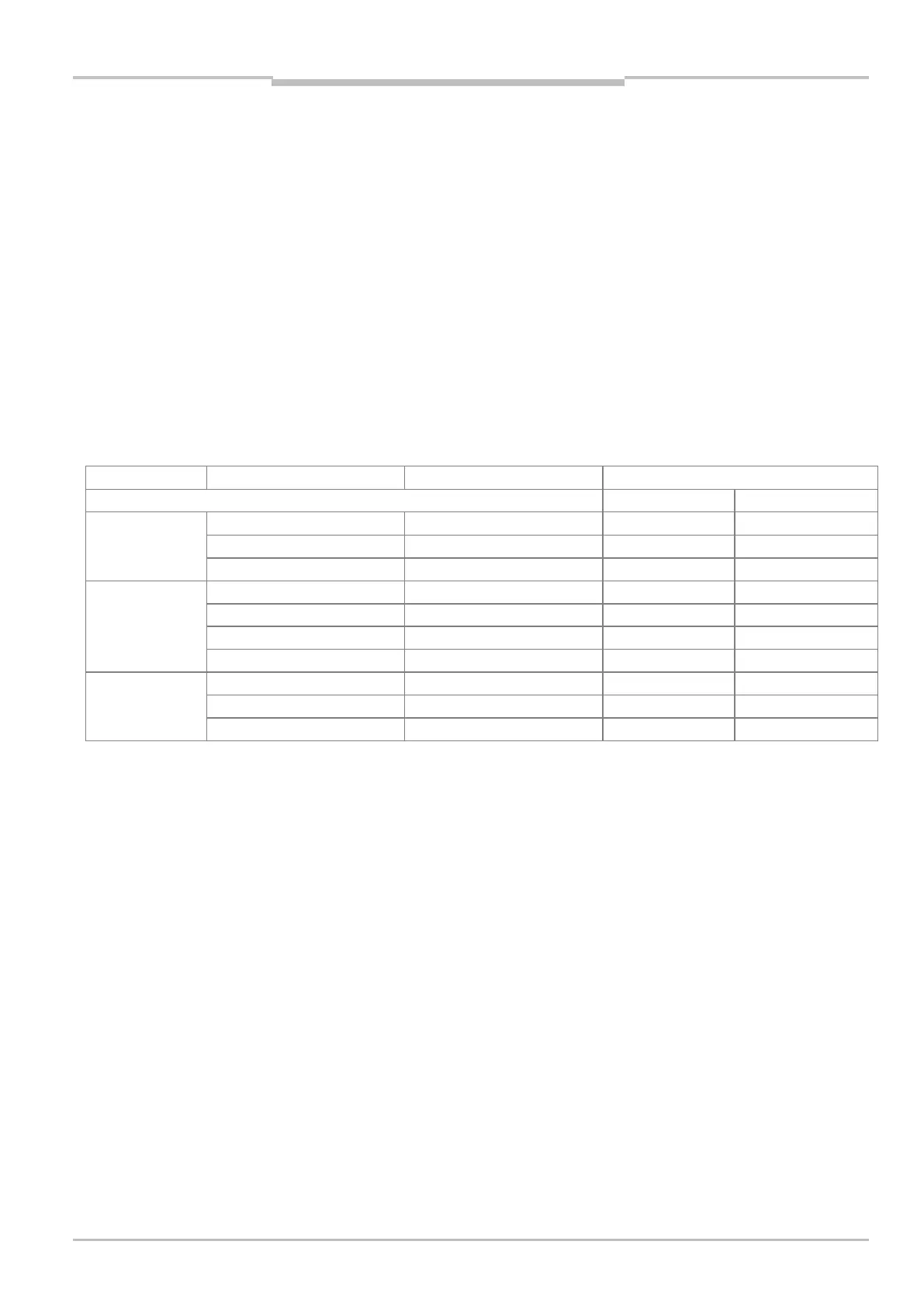
5.4.2 Terminal strips
The terminals have the following wire cross-sections:
MSC800 type Spring force terminal block Function Cable cross-section
Rigid cable Flexible cable
MSC800-1100
MSC800-2100
-X100 Mains voltage IN 0.08 ... 6 mm
2
0.08 ... 4 mm
2
2
2
2
2
MSC800-2300 -X100 Mains voltage IN 0.08 ... 6 mm
2
0.08 ... 4 mm
2
-X120 Supply voltage OUT 0.08 ... 2.5 mm
2
0.08 ... 2.5 mm
2
2
2
2
2
MSC800-3400
MSC800-3600
-X100 Mains voltage IN 0.08 ... 6 mm
2
0.08 ... 4 mm
2
-X120 Supply voltage OUT 0.08 ... 2.5 mm
2
0.08 ... 2.5 mm
2
2
2
Tab. 30 Terminals: applicable wire sections
For secure contacting, do not use any wire ferrules when laying the open wire ends of
flexible cables to the spring force terminals.
Important