Chapter 4
MSC800
8011540/14B8/2019-06-06 Operating instructions | SICK 41
Subject to change without notice
4.4 Mounting of external components
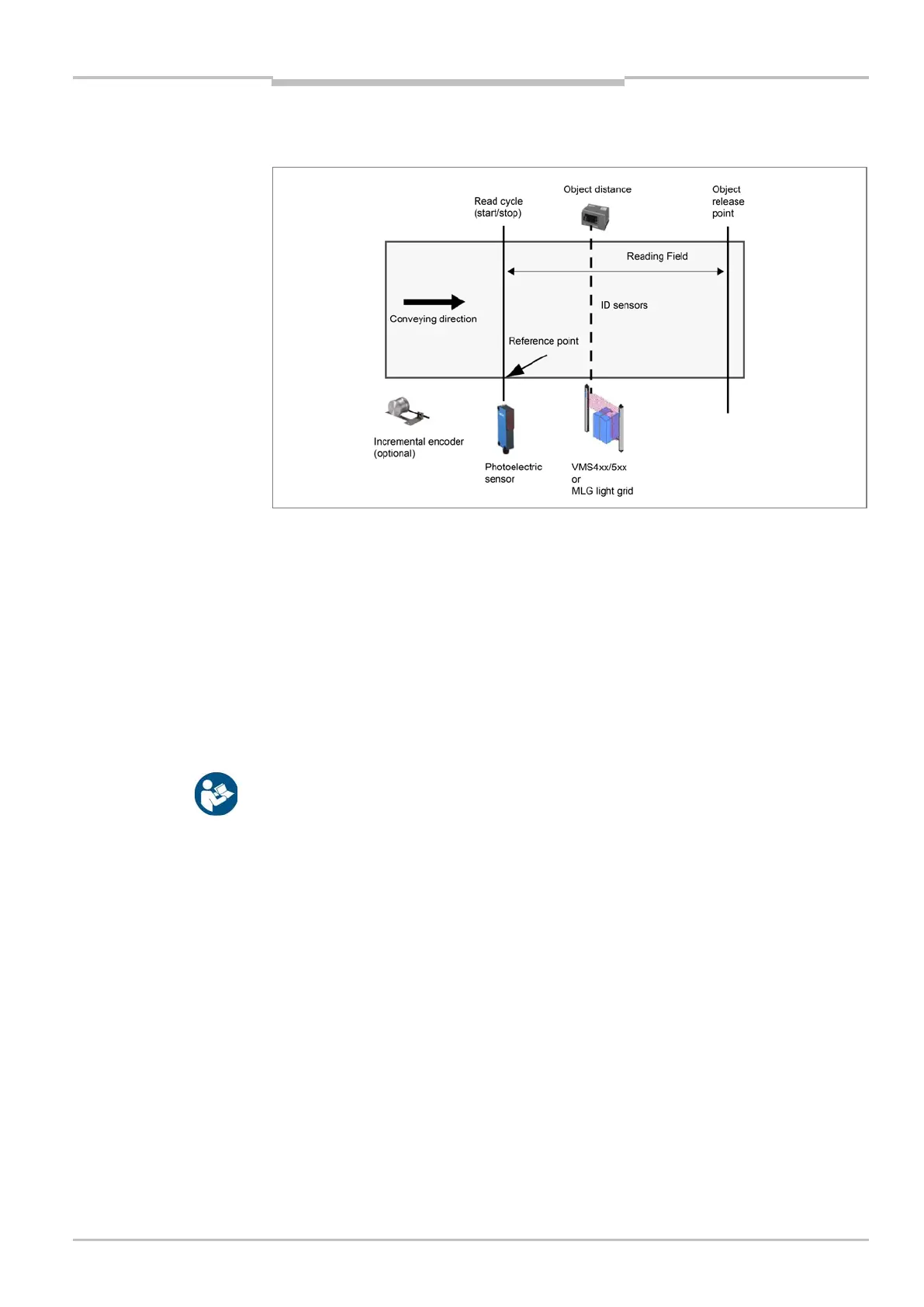
Fig. 15: Position of external components
4.4.1 Mounting ID sensors
The placement of the ID sensors depends on project-specific requirements and on the
number of sensors.
1. For each ICR890 system, mount a unit of illumination and camera together with a
deflector mirror on the mounting frame.
2. Mount the CLV490 bar code scanner according to the information in the project-specific
dimensional drawing.
For additional information see the “High-End CCD Camera System ICR890” (no. 8011324,
German version) and “Bar Code Scanner CLV490” (no. 8009992, German version)
operating instructions.
4.4.2 External sensors for triggering
The read cycle sensor (photoelectric sensor) is mounted on the right edge of the conveying
line according to information in the project-specific dimensional drawing. The position of
the photoelectric sensor is the reference point for the position of the other components.
As much as possible, the photoelectric sensor must be vertical to the conveying direction.
Mount the photoelectric sensor on the conveying line.