Chapter 9
MSC800
90 Operating instructions | SICK 8011540/14B8/2019-06-06
Subject to change without notice
9 Technical data
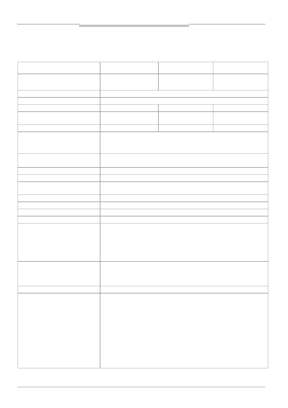
9.1 MSC800 data sheet
Type MSC800-1100
MSC800-2300 MSC800-3400
Function
1)
supply unit for max. 14
1)
supply unit for CLV network
unit for max. two/three
MTBF of the device > 80,000 h
MTTR of the device < 5 min (per component)
Number of ICR890 systems per logic unit
Number of CLV490 bar code scanners
24 24 –
Number of VMS per logic unit 1 1 –
Optical indicators
2 × LED per power supply unit module
6 x LED fuse module (12-pin terminal block), only MSC800-1100/-2100/-2300
48 x LED logic unit
Function of the LEDs chapter 3.5.2 Function of the LEDs on page 35
“Host 1/2” data interface Serial: RS-232, RS-422/485, Ethernet, Profibus-DP
Data format (serial) and output format can be adjusted
Data transmission rate, serial
0.3 ... 115.2 kBd (RS-232, RS-422/485)
Logs SICK Standard, application-specific protocols on request
“AUX 1/2” data interface
Serial: RS-232, RS-422/485 (57.6 KBd); Ethernet
Data format (serial) and output format can be adjusted
Data transmission rate, serial 0.3 ... 115.2 kBd (RS-232, RS-422/485)
“Ethernet” data interface
10/100 MBit/s, TCP/IP, FTP, half/full duplex
“PROFIBUS-DP” data interface 12 MBd
“CAN” data interface 2 x, 20 KBit/s ... 1 MBit/s, CANopen® protocol, CAN SENSOR network
Digital switching inputs IN
14 x digital (6 x IN, 4 x TRIGGER, 4 x INC), configurable, PNP, opto-decoupled,
U
emax
= 28 V, reverse polarity protected
Function: start/stop read cycle, incremental signal, etc.
Control: time-based or route-based
Debouncing: min. 3 ms
Logic level can be selected (Low -> High, High -> Low)
Digital switching outputs OUT
4 x digital, configurable, PNP, I
amax
= 100 mA, short-circuit protected
Function: Device Ready (stat.), System Ready, Good Read, No Read, Temperature, etc.,
pulse duration can be adjusted (stat., 0 ... 65,535 ms or 0 ... 10,000 mm)
Logic level can be selected (Low -> High, High -> Low)
Relay outputs OUT 2 x relay, U
Switch
= max. DC 30 V, I
Switch
= max. 1 A
Electrical connections
1 x service socket (only MSC800-1100/-2100, MSC800-2300)
Supply voltage IN: -X100 terminal block
Supply voltage OUT: -X120 terminal block
Supply voltage OUT: 12-pin terminal block (only MSC800-1100/-2100/-2300)
Logic unit:
1 x 9-pin D-Sub male connector (AUX 1)
3 x 8-pin RJ45 female connector (ETHERNET)
2 x USB female connector, type B
1 x 9-pin D-Sub female connector (PROFIBUS-DP)
9 × double row terminal blocks, pluggable
(all terminals as spring-loaded terminals, for permitted wire cross sections, see chapter
5.4.1 Wire cross-sections on page 57)