Chapter 5
MSC800
44 Operating instructions | SICK 8011540/14B8/2019-06-06
Subject to change without notice
5.2 Electrical installation of the MSC800
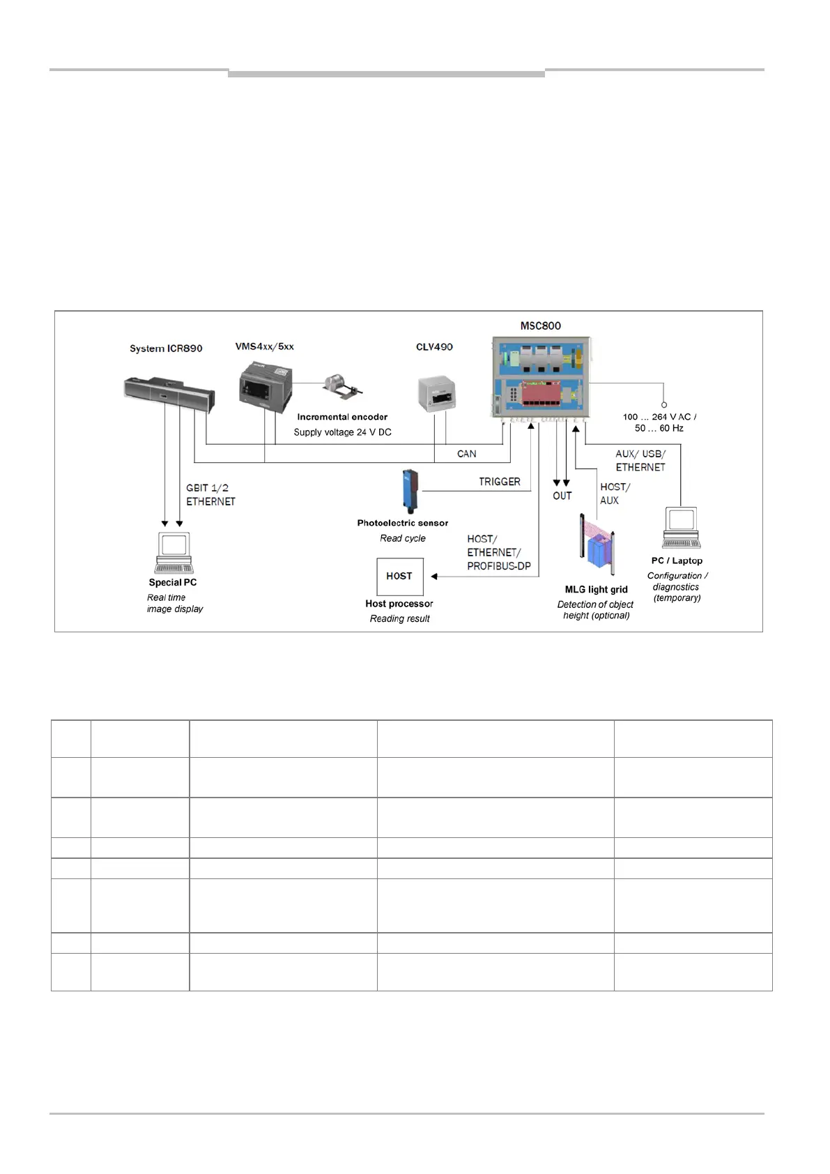
The MSC800 is used in combination with ID sensors for single-side or multi-side reading.
This chapter provides a schematic description of these application possibilities with a
block circuit diagram and a wiring table. The terminals for the DC 24 V supply voltage and
the connections on the logic unit of the MSC800 are described in chapter 5.3 Electrical
connections on page 45. Instructions on carrying out the individual installation steps are
provided in chapter 5.4 Performing the electrical installation on page 56.
Fig. 16: Block circuit diagram: connection principle for an MSC800
Wiring of the MSC800
The following connections must be produced on the MSC800:
No. Connection to
Function Connection with ... Cable to be used
1 Terminal block
-X100
Supply voltage of the MSC800 Mains voltage AC 100 ... 264 V/
50 ... 60 Hz
Customer cable
2 Terminal blocks Supply voltage for ICR890,
CLV490, and VMS4xx/5xx
ICR890 system (POWER IN connection)/
corresponding wires of the CAN cable
(ICR890 scope of delivery)
3 CAN Communication with sensors External sensors (ICR890 scope of delivery)
Read cycle trigger signals
External read cycle sensor
(ICR890 scope of delivery)
5 HOST or
ETHERNET or
PROFIBUS
Data output of the
reading result
Host computer (RS-232, RS-422/485,
or Ethernet)
Customer cable
6 OUT Signaling system status PLC (optional) Customer cable
7 AUX or USB or
Configuration/diagnostics Temporary with standard PC Customer cable
Tab. 10 MSC800: overview of connections to be made on the MSC800