Chapter 5
MSC800
8011540/14B8/2019-06-06 Operating instructions | SICK 67
Subject to change without notice
Example for wiring of the CAN 1 data interface with an ICR890 system:
Connect ICR890 system via CAN 1-IN connection with cable no. 6021166 with 5-pin
M12 female connector and open end. (For pin/wire color assignment, see chapter 5.5.2
Assignment of wire colors of assembled cables with open end on page 72.)
Place the free wire end in the MSC800 on the CAN 1 connection.
Attach termination resistor no. 6021167 to the CAN 1-OUT connection of the ICR890
system.
The signals for read cycle and increment are transmitted to the ICR890 system via the
CAN bus. The HOST and AUX data interfaces of the ICR890 system and the signals of the
two switching outputs are accessible via the CAN bus on the MSC800. For this purpose,
the MSC800 and the ICR890 systems must be configured as master/slave accordingly
(see chapter 6.3 Initial commissioning on page 75).
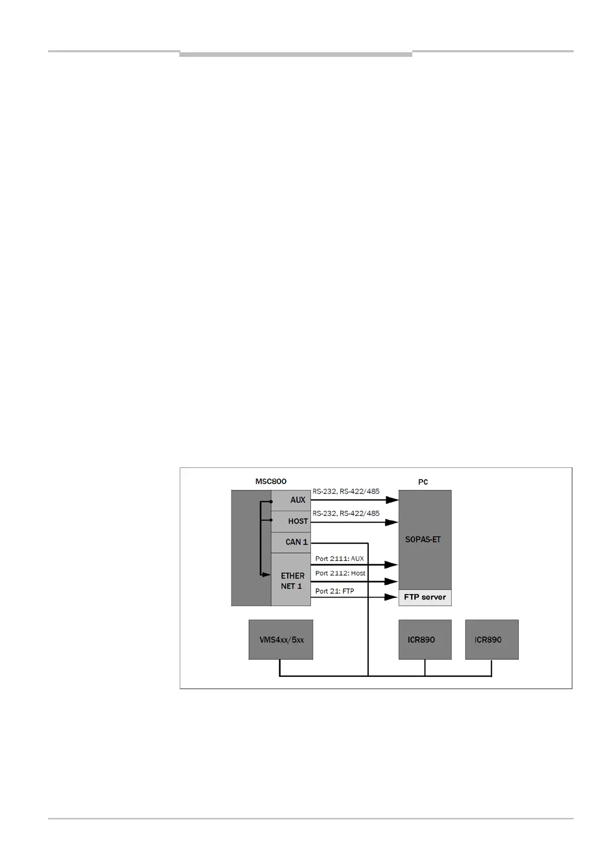
5.4.10 ETHERNET 1 Ethernet interface of the logic unit
The ETHERNET 1 Ethernet interface of the MSC800 has several functions:
• Output of the read result of the HOST data interface via TCP/IP in parallel to the serial
RS-232, RS-422/485 interface design
• Output of the data from the AUX data interface (reading result + reading diagnostic
data) via TCP/IP in parallel to the serial RS-232, RS-422/485 interface design
• Access to the MSC800 with the SOPAS-ET configuration software
• Connection as RDT400 client (system remote monitoring).
Fig. 26: Block circuit diagram: function of the Ethernet interface