Chapter 5
MSC800
68 Operating instructions | SICK 8011540/14B8/2019-06-06
Subject to change without notice
Connecting ETHERNET 1 Ethernet interface of the logic unit
Use the cross-over cable (see chapter 10.3.2 Accessories: pre-wired cables for CAN
SENSOR Network on page 120) to connect the MSC800 directly to the Ethernet card of
the PC (point-to-point connection).
- or -
Use the standardized data cable (patch cable) to connect the MSC800 to the Ethernet
network.
For the settings required on the PC and on the MSC800, see chapter 6.3.2 Establishing
communication with the MSC800 on page 76.
5.4.11 IN, TRIGGER, and INC switching inputs of the logic unit
The connection of the read cycle sensor is carried out via one of the digital switching
inputs TRIGGER_1 to TRIGGER_4. The incremental encoder is connected to one of the
digital switching inputs INC 1 to INC 4 (maximum switching frequency 30 KHz).
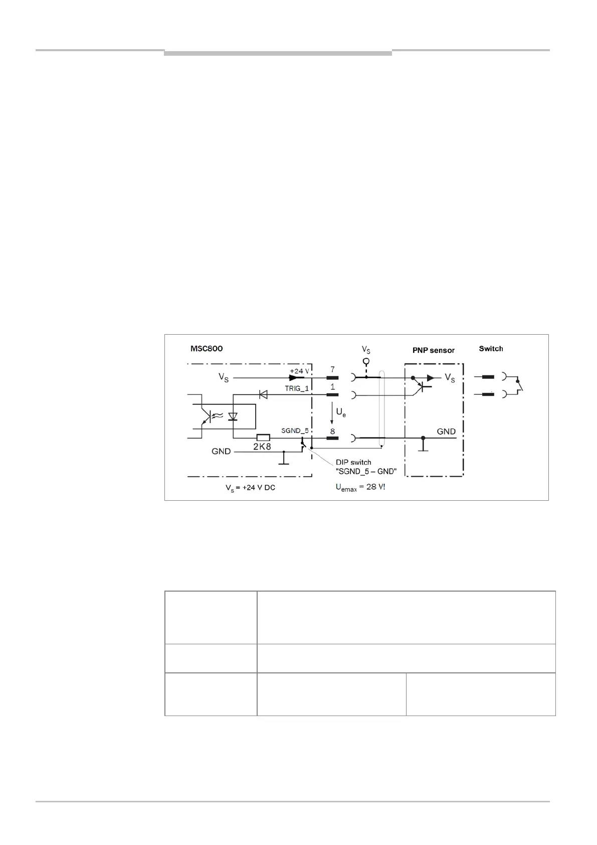
The following figure shows an example of the wiring of switching input TRIGGER_1.
Fig. 27: Wiring of switching input TRIGGER_1
If the read cycle sensor is supplied with an external voltage, the connection of the
switching output to the MSC800 can take place volt-free (DIP switch SGND_5–GND to
OFF, connection to terminal 7 is not present).
The table below contains the characteristic data for the input.
Switching behavior TRIGGER_1: current at the input starts the reading interval, if function is
assigned via SOPAS-ET configuration software
(Default: not inverted (active high); debouncing: 10 ms; delay cycle start:
0 ms/0 mm, PSDI end: 0 ms/0 mm)
Properties – Opto-decoupled, reverse-polarity protected
– Can be wired with PNP output of a sensor
Electrical values Low:
–1 V ≤ U
e
≤ +1 V
≤
e
≤
High
+8 V ≤ |U
e
| ≤ +28 V
≤
e
≤
Tab. 43 Characteristic data for switching input TRIGGER_1
The characteristic data (properties, electrical values) of switching inputs TRIGGER_2 to _4,
INC_2 to INC_4, and IN_1 to IN_6 are identical to that of TRIGGER_1.