Chapter 5
MSC800
8011540/14B8/2019-06-06 Operating instructions | SICK 59
Subject to change without notice
5.4.4 Applying the shield
In order to connect the cable shield with the housing of the MSC800, proceed as follows:
MSC800 type View Cable entry
MSC800-1100
MSC800-2100
24 V DC supply voltage to CLV490/VMS4xx/5xx via the CAN bus cable
On the metal cable entries on the
bottom of the housing
Other cables with shield braid
MSC800-2300 24 V DC supply voltage to ICR890 Terminal -X120/17 to -X120/19
24 V DC supply voltage to CLV490/VMS4xx/5xx via the CAN bus cable On the metal cable entries on the
bottom of the housing
Other cables with shield braid
MSC800-3400 Supply voltage OUT 1 (DC 24 V) to ICR890 (system 1) Terminal -X120/17 to -X120/19
Supply voltage OUT 2 (DC 24 V) to ICR890 (system 2) Terminal -X120/27 to -X120/29
24 V DC supply voltage to CLV490/VMS4xx/5xx via the CAN bus cable On the metal cable entries on the
bottom of the housing
Other cables with shield braid
MSC800-3600
Supply voltage OUT 1 (DC 24 V) to ICR890 (system 1)
Terminal -X120/17 to -X120/19
Supply voltage OUT 2 (DC 24 V) to ICR890 (system 2) Terminal -X120/27 to -X120/29
Supply voltage OUT 3 (DC 24 V) to ICR890 (system 3) Terminal -X120/37 to -X120/39
24 V DC supply voltage to CLV490/VMS4xx/5xx via the CAN bus cable
On the metal cable entries on the
bottom of the housing
Other cables with shield braid
Tab. 32 Connection of the cable shields on the MSC800
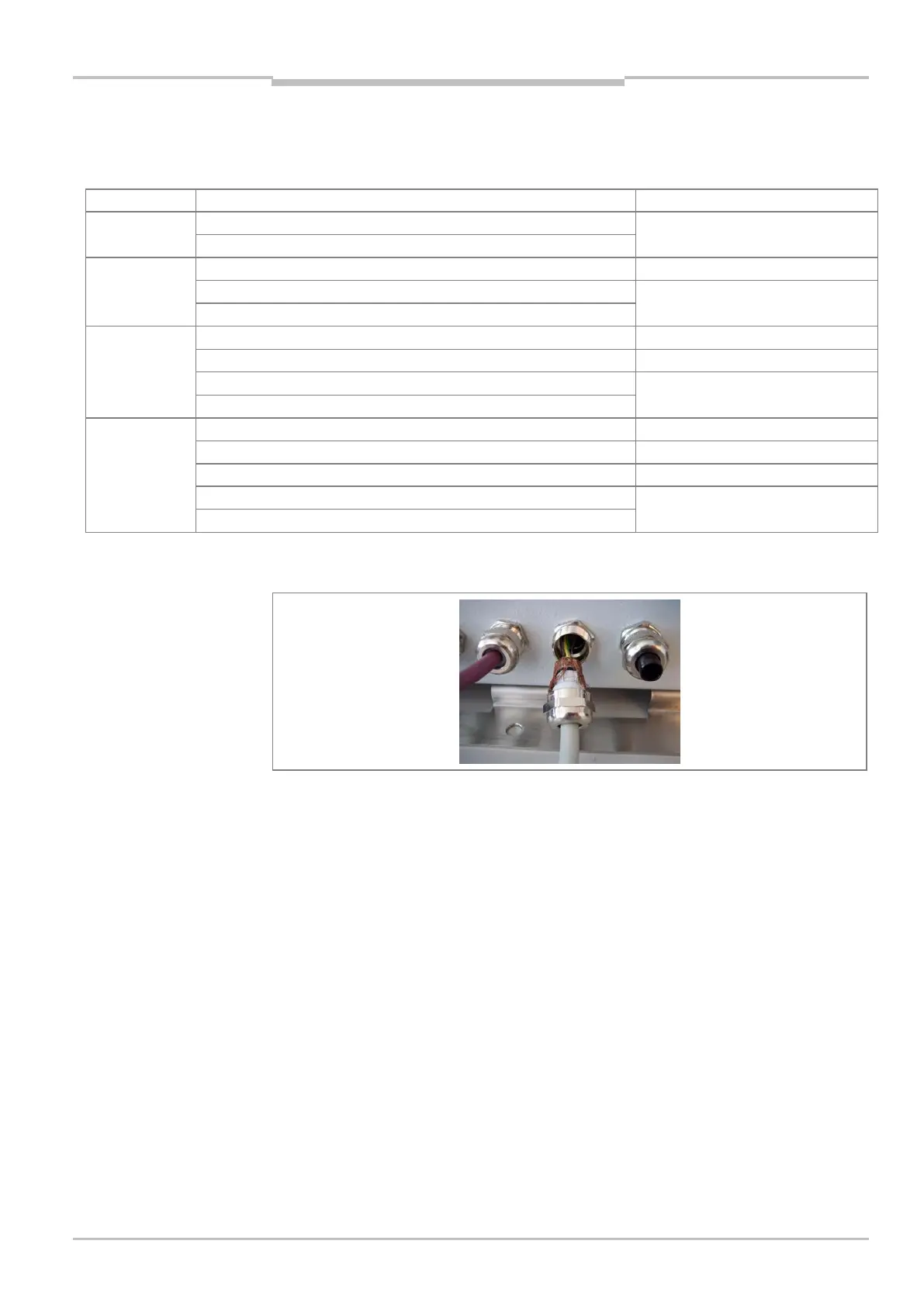
Fig. 23: Connecting the cable shields at the inlet to the housing
Shielded cables must be used for the following connections, and their shielding must be
laid on the housing in the cable entry:
• Serial data interfaces (RS-232, RS-422/485)
• Ethernet interface
• CAN interfaces
• Profibus interface
• Digital switching inputs (e.g., incremental encoder, read cycle sensor).
Individual components of the MSC800-0000 logic unit
For electrical connection of the MSC800-0000 logic unit in the event of customer
installation into a control cabinet, observe the installation regulations in chapter 4.3.2
Mounting individual components of the logic unit on page 40.