Chapter 3
MSC800
8011540/14B8/2019-06-06 Operating instructions | SICK 35
Subject to change without notice
Parameter set on the SD memory card
The configured parameter values are saved as a parameter set in the internal EEPROM of
the MSC800 and on the SD memory card (SD 1) of the logic unit (cloning). If the logic unit
has to be replaced, the memory card makes transferring the parameter set to the new
device quick and easy (see chapter 7.5 Replacing components of the MSC800 on
page 84).
In order to avoid data loss, the SD memory card may only be removed from or inserted into
the new device when the MSC800 is switched off.
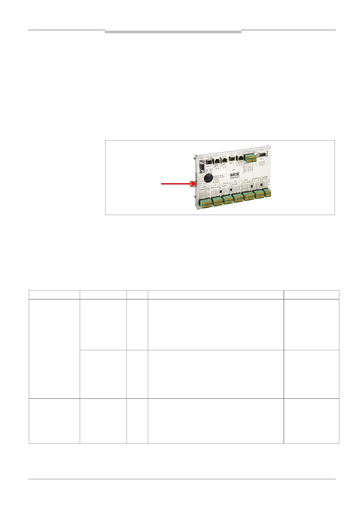
The card can be accessed on the left side of the MSC800 logic unit.
Fig. 11: Position of the SD memory card for parameter set on the MSC800-0000 logic unit
3.5.2 Function of the LEDs
The accessible LEDs of the MSC800 are on the power supply unit modules, on the fuse
module for the supply voltage DC 24 V (CLV490, VMS4xx/5xx, logic unit; only MSC800-
1100, MSC800-2100 and MSC800-2300), and on the logic unit.
Installation site LED Color Meaning Note
Power supply unit
modules
DC ok Green ON: power supply unit ready for operation
OFF: no input voltage (mains voltage)
ON: voltage drop, short-circuit
“Overload” LED lights up
OFF: shutdown due to overheating
“Overload” LED flashing
If OFF, remove cause
(lack of input
voltage/overload)
Overload Red OFF: power supply unit ready for operation
ON: voltage drop, short-circuit
Flashing: power supply unit overheated
The power supply unit module disconnects the DC 24 V
output voltage from the consumer by means of the
internal relay.
Remove the cause of
the overload
Fuse module
DC 24 V supply
voltage
Fault
(F1 to F6)
Red The LEDs light up if the fuse for the relevant terminal
is defective. The fuses are assigned to the terminals as
follows:
F1/terminal 11+, F2/terminal 12+, F3/terminal 13+,
F4/terminal 14+, F5/terminal 15+, F6/terminal 16+
Only MSC800-
1100, -2100,
-2300
Remove cause
of overload and
Important