Chapter 3
MSC800
20 Operating instructions | SICK 8011540/14B8/2019-06-06
Subject to change without notice
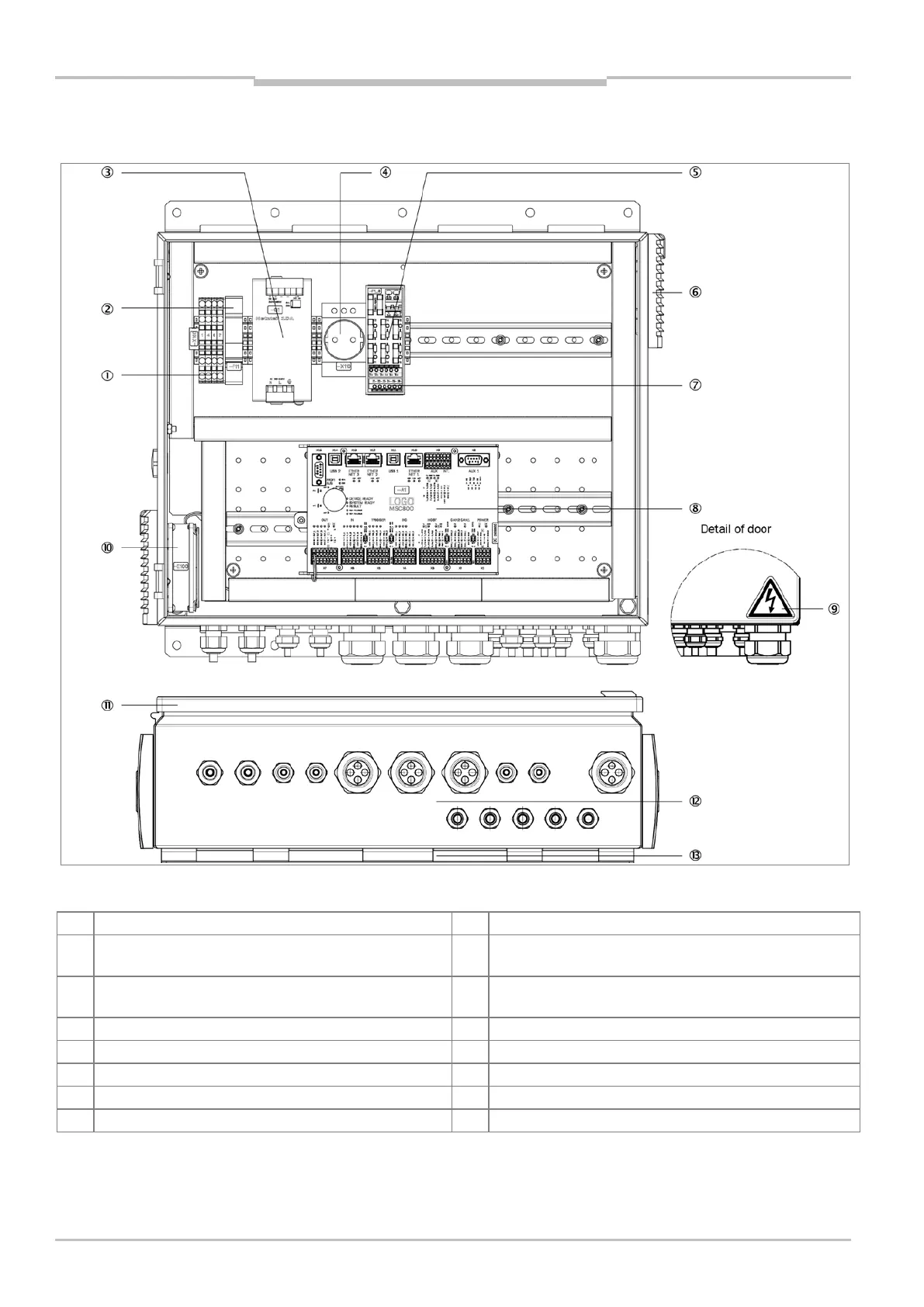
3.1.2 MSC800-2100 device view
Fig. 3: MSC800-2100 device view (internal view with open door and view from below)
1 Terminals for mains voltage IN (AC 100 ... 264 V /
50 ... 60 Hz)
8 Logic unit with connections and SD memory card for
parameter cloning
2 Circuit breaker for protective contact socket and power
supply unit module
9 “Hazardous electrical voltage” warning symbol
Power supply unit module 10 A for supply voltage DC 24 V
Air inlet for cooling (with fan and filter mat)
Protective contact socket (mains voltage)
5 Fuses for supply voltage OUT DC 24 V 12 Cable entries (M screw connections)
6 Air outlet for cooling (with filter mat) 13 Perforated sheet for mounting (2 x)
Terminals for supply voltage OUT (DC 24 V, max. 10 A)