Chapter 5
MSC800
62 Operating instructions | SICK 8011540/14B8/2019-06-06
Subject to change without notice
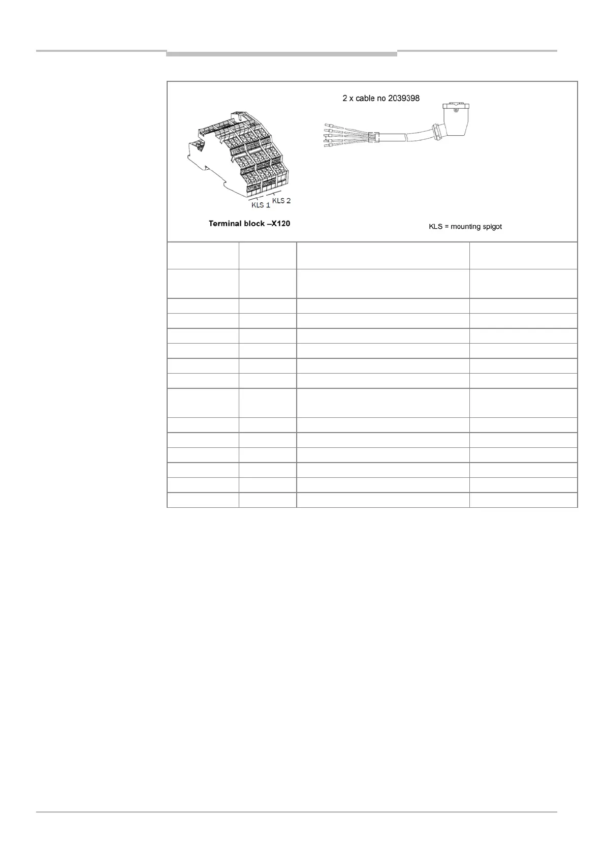
System/
terminal set
Terminal Signal Wire color (numbers
printed on wires)
System 1
-X120/11 DC +24 V (ICD890 camera) Wire 1: black
-X120/13 DC +24 V (ICI890_1#1 illumination) Wire 3: black
-X120/14 GND (ICI890_1#1 illumination) Wire 4: black
DC +24 V (ICI890_1#2 illumination)
GND (ICI890_1#2 illumination)
-X120/17 PE Green-yellow
System 2
KLS2
-X120/21 DC +24 V (ICD890 camera) Wire 1: black
-X120/22 GND (ICD890 camera) Wire 2: black
DC +24 V (ICI890_2#1 illumination)
-X120/24 GND (ICI890_2#1 illumination) Wire 4: black
-X120/25 DC +24 V (ICI890_2#2 illumination) Wire 5: black
GND (ICI890_2#2 illumination)
Tab. 36 MSC800-3400: connection of the supply voltage cables for two ICR890 systems