M90 Fusion Splicer 1-6 Operating Instructions
Getting to Know the M90 Fusion Splicer Issue 02/97
Splicing Unit
Overview
Overview of Fusion Unit
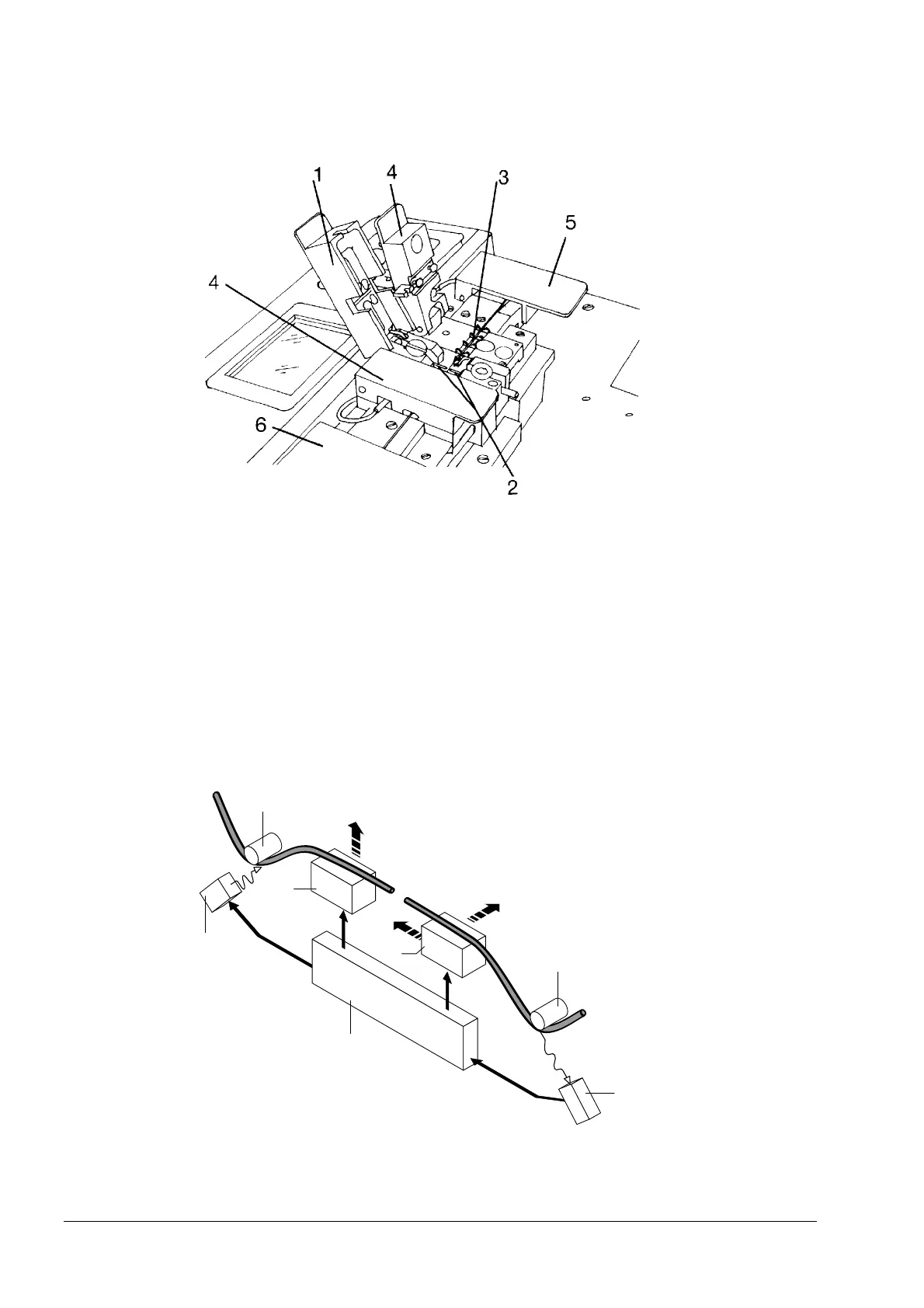
Fusion unit
1 Electrode flap
with illumination
2 Electrodes
3 Fiber guides
4 Holder flap
LID system
5 Transmitter
6 Receiver
LID system
The LID system allows exact core-to-core positioning. It consists of a transmitter and a
receiver. The optical fibers that are to be connected are inserted into the transmitter
and receiver. Located in the LID flaps there are the mandrels for bending the optical
fibers.
Principle Light can normally be launched into the core of a straight fiber only at its end face. If the
fiber is bent around a sufficiently small radius, however, such as occurs here at the
mandrels of the holder flaps, light can be launched into or extracted from the fiber
through the primary coating.
Principle of the LID System
X X axis
Y Y axis
Z Z axis
1 Mandrel
2 Receiver
(photodiode)
3 Microprocessor
4 Positioning ele-
ments
5 Transmitter (LED)
Artisan Technology Group - Quality Instrumentation ... Guaranteed | (888) 88-SOURCE | www.artisantg.com