M90 Fusion Splicer 2-12 Operating Instructions
Preparations Issue 02/97
Inserting the Optical Fibers into the LID System
If the use of the LID system is not required and no tensile test is performed, the fibers
need not be inserted into the LID system, e.g. in the case of fusion with program groups
"Fixed parameters (video)" or fusion with external attenuation test set.
Cleanliness
- Open the transmitter and receiver flap.
Check the cleanliness of:
mandrels,
groove and
input face / output face (see figure below).
- Clean the parts if necessary (see section 7).
Note
Maximum permissible fiber diameter: 250 µm over coating.
Index-matching
fluid
To increase the efficiency of light injection and detection, the input and output areas are
coated with index-matching fluid.
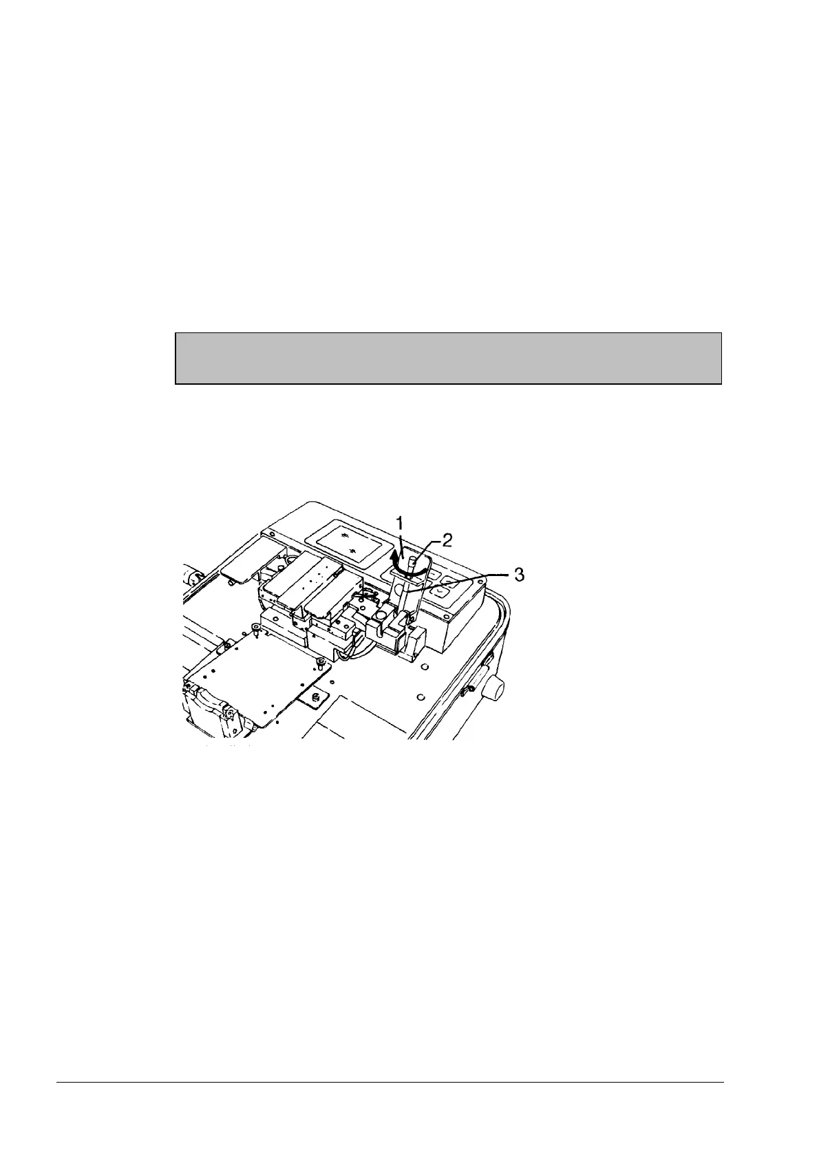
A metering wheel (2) is provided on the mandrel for this purpose.
Metering the Index-Matching Fluid
1 Flap
2 Metering wheel
3 Groove (emergence
of index-matching
fluid)
- To wet the input and output areas with index-matching fluid, turn the metering wheel
(2) slowly in clockwise direction until a small drop appears in the groove of the man-
drel (3).
Top up if no fluid emerges (section 7).
- Close the flap (1) in order to wet the input and output areas with the index-matching
fluid.
Inserting the
fibers
- Open the flap (1).
- Insert the fiber in the groove and hold it under slight tension.
- Slowly and carefully close the flap (1).
Now insert the second fiber into the receiver in exactly the same way.
Artisan Technology Group - Quality Instrumentation ... Guaranteed | (888) 88-SOURCE | www.artisantg.com