05.05 Connections
Siemens AG 6RX1700-0AD76 6-71
SIMOREG DC Master Operating Instructions
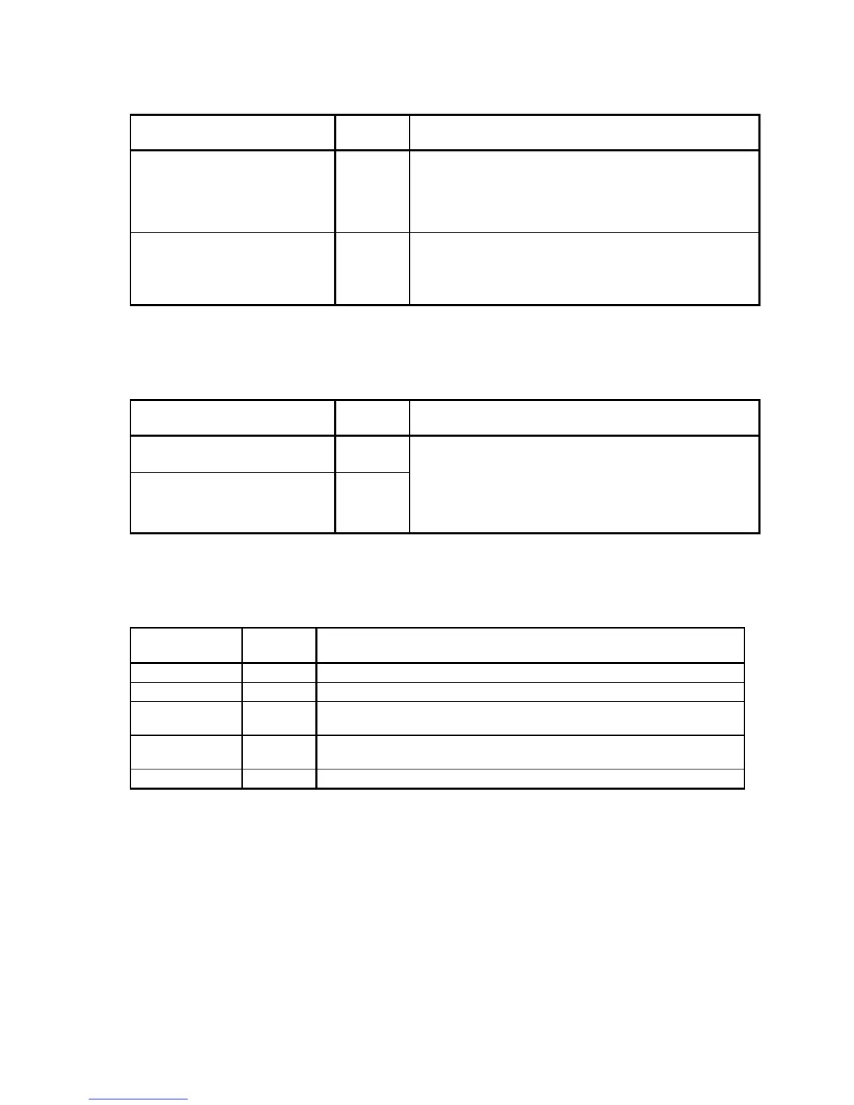
Binary inputs (see also Section 8, sheet G111)
Module C98043-A7006 CUD2
Function Terminal
X163
Connection values/Remarks
Supply 44 24V DC, short circuit proof
max. load 200mA (terminals 34, 44, and 210 combined),
internal supply with respect to internal ground
Ground digital M 45
Overload response: Error signal F018
Warning signal A018
Select input binary 3 40
Select input binary 4 41
Select input binary 5 42
Select input binary 6 43
H signal: +13V to +33V
L signal: – 33V to +3V or terminal open
8.5mA at 24V
Binary outputs
(see also Section 8, sheet G112)
Module C98043-A7006 CUD2
Function Terminal
X163
Connection values/Remarks
Select output binary 3
Ground M
50
51
Select output binary 4
Ground M
52
53
H signal: +20V to +26V
L signal: 0 to +2V
Short-circuit-proof 100mA
Overload response: Error signal F018
Warning signal A018
Internal snubber circuit (free-wheeling diode)
Serial interface 3 RS485 (G-SST3)
Module C98043-A7006 CUD2
Function Terminal
X162
Connection values/Remarks
TX+ 61 RS485, 4-wire send cable, positive differential output
TX- 61 RS485, 4-wire send cable, negative differential output
RX+/TX+ 63 RS485, 4-wire receive cable, positive differential input,
2-wire send/receive cable, positive differential input
RX-/TX- 64 RS485, 4-wire receive cable, negative differential input,
2-wire send/receive cable, negative differential input
M 65 Ground
Cable length: For transmission rate =187.5kBd
⇒ 600m
For transmission rate
≤93.75kBd ⇒ 1200m
The following must be observed: DIN 19245 Part 1
The potential difference between the data reference potentials M of all interfaces must not
exceed -7V / +12V. If this cannot be guaranteed, then equipotential bonding must be
provided.
Activate interface 3:
– Set the baud rate in parameter P803.
– Set the protocol in parameter P800.

 Loading...