Function diagrams 05.05
8-48 SIEMENS AG 6RX1700-0AD76
SIMOREG DC Master Operating Instructions
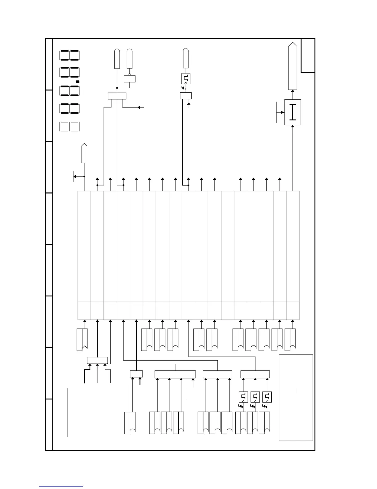
Sheet G180 Control word 1
&
&
1
≥
321Bit0
4567
Bit8910
11
12131415
&
1
≥
8
7
564321
- G180 -
1
&
[G136.3]
[G136.2]
[G136.1]
[G129.2]
[G129.2]
[G135.6]
[G135.6]
[G126.2]
[G126.2]
[G117.7]
[G110.5]
[G130.7]
[G130.7]
[G129.7]
[G140.3]
[G140.3]
[G136.1]
[G161.1]
Bit 0
Bit 1
Bit 2
Bit 3
Bit 4
Bit 5
Bit 6
Bit 7
Bit 8
Bit 9
Bit 10
Bit 11
Bit 12
Bit 13
Bit 14
Bit 15
P667.B (0)
B
P666.B (0)
B
P665.B (0)
B
B
B
B
B
B
P655.B (1)
B
P656.B (1)
P657.B (1)
P658.B (1)
P659.B (1)
P660.B (1)
P675.B (1)
B
P674.B (0)
B
P673.B (0)
B
P672.B (1)
B
P671.B (1)
B
P668.B (0)
B
P669.B (0)
B
P661.B (1)
B
P662.B (1)
B
P663.B (1)
B
P664.B (1)
B
<1>
<1>
r650
K0030
P360.01 (0ms)
(0...10000ms)
P648.B (9)
K
B0160
B0161
150ms
1
≥
B0179
0=OFF1, shutdown via ramp-function generator followed by
pulse disable
1=ON, operating condition (edge-controlled)
0=OFF2, pulse disable, motor coasts to standstill
1=operating condition
0=OFF3, fast stop
1=operating condition
1=Enable, enable pulses
0=Pulse disable
1=Enable ramp-function generator
0=Set ramp-function generator to 0
1=Ramp-function generator start
0=Ramp-function generator stop
1=Enable setpoint
0=Disable setpoint
0 =>1 edge Acknowledge
1=Inching bit 0
1=Inching bit 1
1=Control by PLC
0=No control by PLC
1=Enable positive direction of rotation
0=Positive direction of rotation disabled
1=Enable negative direction of rotation
0=Negative direction of rotation disabled
1=Increase motorized potentiometer
1=Decrease motorized potentiometer
0=External fault 1 (F021)
1=No external fault
Bit No.
Meaning
Pulse generator
Control word 1
Control word 1
to sequencing control
to sequencing control
to sequencing control
to sequencing control,
to brake control
to sequencing control,
to brake control
Enable operation
(from Sheet "Binary inputs 1")
Display of control word 1 (r650)
on 7-segment display
External fault 1
Fault F021
to sheet
"Ramp-function generator"
to sheet "Ramp-function generator"
to sheet "Ramp-function generator"
to sheet "Setpoint processing"
to sheet "Setpoint processing"
to sheet
"Motorized potentiometer"
to sheet
"Motorized potentiometer"
to sheet "Inching setpoint"
to sheet "Inching setpoint"
Switch-on commmand from ON/OFF1
(from sheet "Crawling setpoint
/ Terminal 37")
Switch-on command from CRAWL
(from sheet "Crawling setpoint")
Switch-on command from INCHING
(from sheet "Inching setpoint")
When P648 = 9, bit-serial input of control bits (P654 to P675 are effective)
When P648 <> 9, word-serial input of control bits (P654 to P675 are not effective)
Terminals 37 and 38 are always active. They are ANDed with bit 0 or bit 3.
E-Stop
from optimization run
from control logic for field reversal
Bit 10 is displayed in connector K0030 and
parameter r650 when control word 1 is
input in word mode. It is
not, however,
functional. The mode of functioning of bit 10
is shown on Sheets G170, G171,
G172, Z110 and Z111
from E-Stop, relay outp.line contactor
P key
(PMU)

 Loading...