05.05 Function diagrams
SIEMENS AG 6RX1700-0AD76 8-49
SIMOREG DC Master Operating Instructions
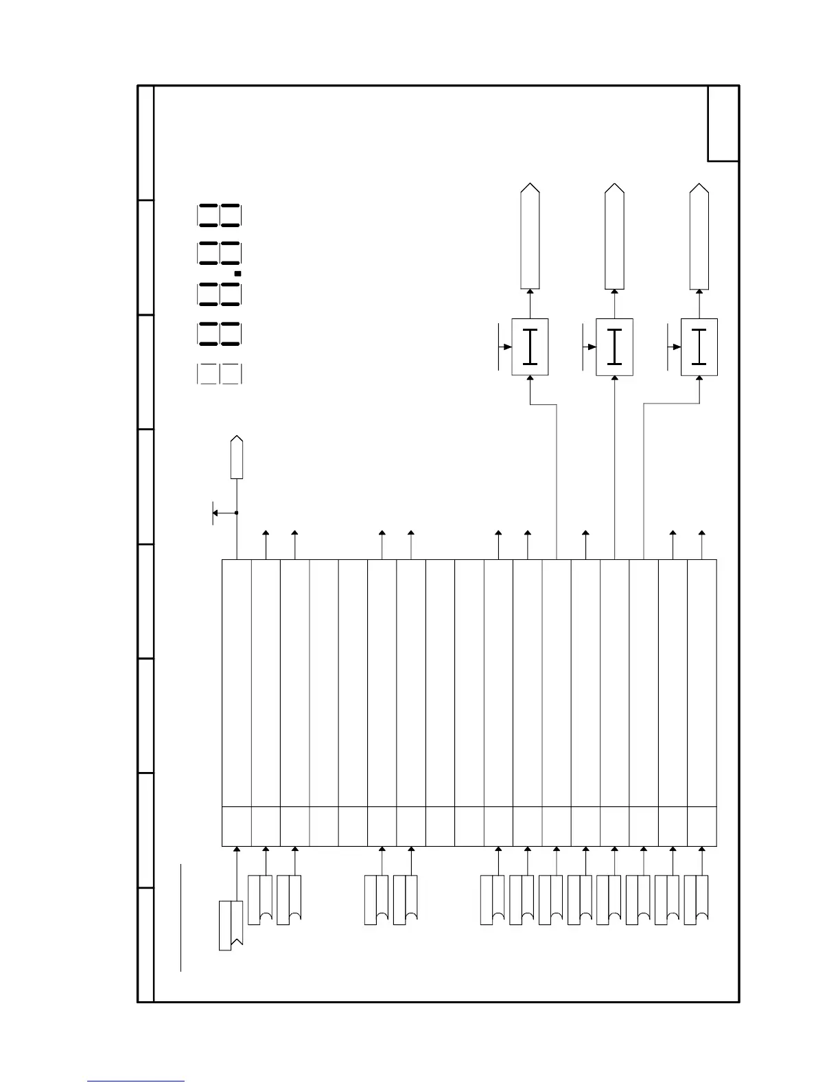
Sheet G181 Control word 2
19 18 17 Bit16
20212223
Bit2425262728293031
8
7
564321
- G181 -
[G175.4]
[G175.4]
[G127.2]
[G127.2]
[G151.6]
[G152.6]
[G160.2] [G152.4]
[G175.4]
Bit 16
Bit 17
Bit 18
Bit 19
Bit 20
Bit 21
Bit 22
Bit 23
Bit 24
Bit 25
Bit 26
Bit 27
Bit 28
Bit 29
Bit 30
Bit 31
P691.B (0)
B
P690 (0)
B
P689.B (1)
B
P688.B (1)
B
P687.B (0)
B
P684.B (1)
B
P685.B (1)
B
P680.B (0)
B
P681.B (0)
B
P676.B (0)
B
r651
K0031
P677.B (0)
B
P686.B (1)
B
P360.02 (0ms)
(0...10000ms)
P360.03 (0ms)
(0...10000ms)
P360.04 (0ms)
(0...10000ms)
P649.B (9)
K
Control word 2
Bit No.
Meaning
Control word 2
Select function data set bit 0
Select function data set bit 1
Spare
Spare
Select fixed setpoint 0
Select fixed setpoint 1
Spare
1=Enable speed controller droop
0=Speed controller droop disabled
1=Enable speed controller
0=Speed controller disabled
0=External fault 2 (F022)
1=No external fault 2
0=Master drive (speed control)
1=Slave drive (torque control)
0=External alarm 1 (A021)
1=No external alarm 1
0=External alarm 2 (A022)
1=No external alarm 2
0=Select Bico data set 1
1=Select Bico data set 2
Main contactor check-back signal
to sequencing control
Spare
Display of control word 2 (r651)
on 7-segment display
External fault 2
Fault F022
External alarm 2
Alarm A022
External alarm 1
Alarm A021
to sheet "Data sets"
to sheet "Data sets"
to sheet "Speed controller (2)"
to sheet "Speed controller (1)"
to sheet "Fixed setpoint"
to sheet "Fixed setpoint"
to sheet "Data sets"
to sheets
"Torque limitation" and
"Speed controller (2)"
When P649 = 9, bit-serial input of control bits (P676 to P691 are effective)
When P649 <> 9, word-serial input of control bits (P676 to P691 are not effective)

 Loading...