Function diagrams 05.05
8-52 SIEMENS AG 6RX1700-0AD76
SIMOREG DC Master Operating Instructions
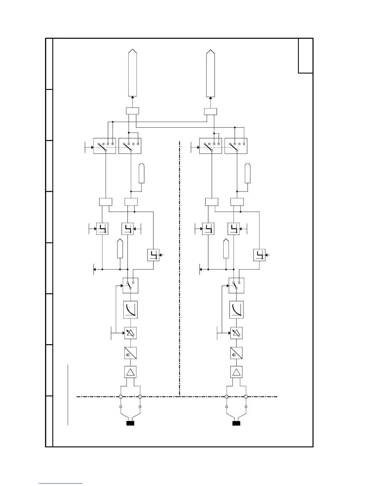
Sheet G185 Motor interface (1)
87564321
204
205
22
23
#
1
≥
1
≥
1
0
2
3
1
0
2
3
- G185 -
X174
X164
<1>
<1>
<1>
<1>
1
≥
1
≥
1
2
<3>
<3>
#
1
2
<4>
<4>
1
0
2
3
1
0
2
3
1
≥
1
≥
<2>
<2>
CUD1
CUD2
01:2
02:2
15:2
01:2
02:2
15:2
<5>
<5>
P491.F
P492.F
r012.02
P490.01
P491.F
P492.F
K0051
r012.01
0,6 s
P490.02
K0052
P493.F
P494.F
B0184
B0185
0,6 s
1...KTY84 (P490.01=1)
2...PTC (P490.01=2,3,4,5)
1...KTY84 (P490.02=1)
2...PTC (P490.02=2,3,4,5)
Motor interface (1)
Motor temperature
alarm (analog)
Motor temperature 1
Select
temperature sensor
Alarm temperature
Trip temperature
Motor temperature
fault analog 1
Motor temperature
alarm analog 1
1 = "Alarm A029"
Motor temperature 2
Select
temperature sensor
Alarm temperature
Trip temperature
Motor temperature
fault analog 2
Motor temperature
alarm analog 2
Motor temperature
fault (analog)
1 = "Fault F029"
(PTC alarm) 01:1
(PTC trip) 02:1
(KTY84) 15:1
(PTC alarm) 01:1
(PTC trip) 02:1
(KTY84) 15:1
<1> Parameter r012 and connectors K0051 / K0052 output valid values only if a KTY84 is selected.
When a PTC is selected, r012 and K0051 / K0052 always output "0".
PTC response temperature
PTC response temperature
<2> Response temperature used depends on the type of PTC
<5> Use a shielded cable and connect it to ground at both ends

 Loading...