05.05 Function diagrams
SIEMENS AG 6RX1700-0AD76 8-53
SIMOREG DC Master Operating Instructions
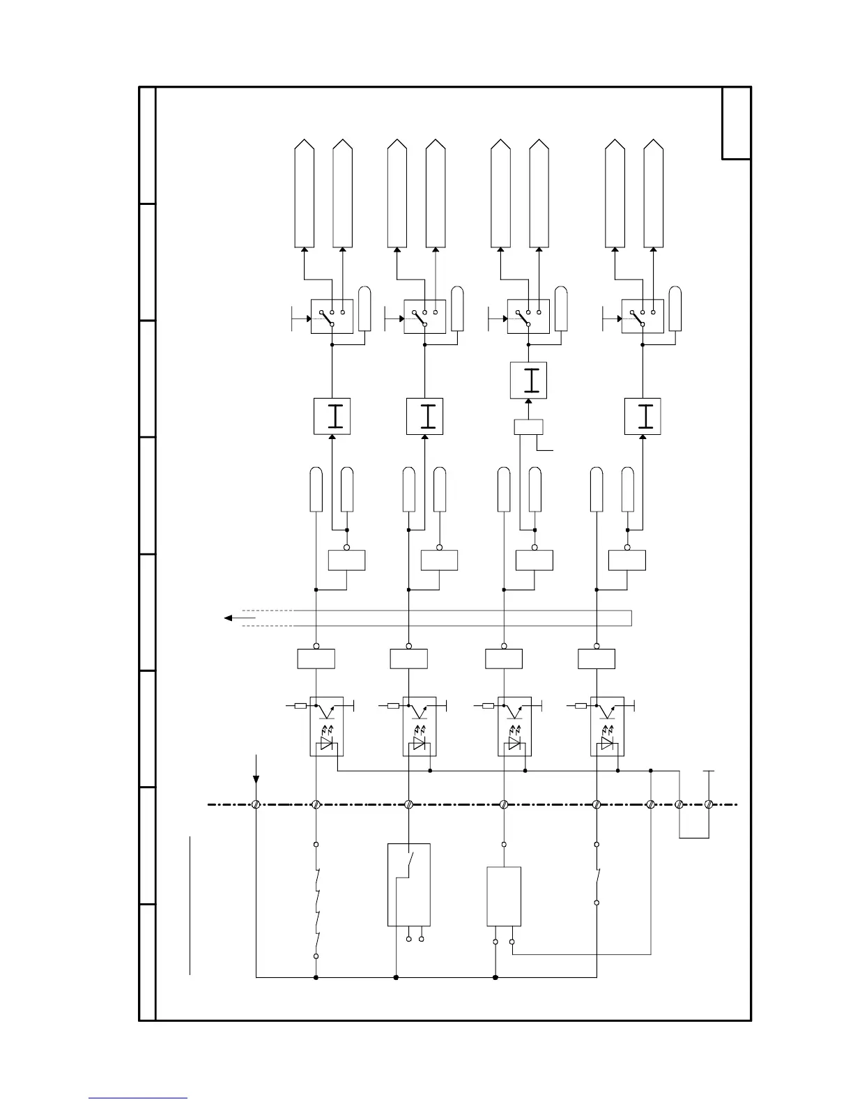
Sheet G186 Motor interface (2) / binary inputs, terminals 211 to 214
210
215
M
1
211
M
+
1
212
M
+
1
213
M
+
1
214
M
+
1
1
1
1
+24V
13:213:1
56:3
56:2
56:1
90:1 90:2
230V ~
1
0
2
1
0
2
1
0
2
<1>
<1>
<1>
T
0
&
<1>
T
0
T
0
T0
1
0
2
216
217
P24_S
87564321
- G186 -
X161
CUD2
B0041
B0040
B0043
B0042
B0045
B0044
B0047
B0046
P495.F
P496.F
P497.F
P498.F
B0181
B0183
B0180
B0182
Motor interface (2)
Binary inputs (3)
For display of terminal states
on 7-segment display , see
block diagram "Binary inputs (1)"
(G110)
Air-flow
monitor
SPM
Alarm box
Brush length fault (binary)
Brush length monitoring (binary)
0 = Fault
Bearing condition monitoring (binary)
1 = Fault
Motor fan monitoring (binary)
0 = Fault
Motor temperature
monitoring (binary)
0 = Fault
Bearing condition
fault (binary)
Bearing condition
alarm (binary)
Motor fan fault (binary)
Motor fan alarm (binary)
40s ON delay
Operating
status < o6
10s ON delay
Brush length alarm (binary)
2s ON delay
10s ON delay
M otor tem perature
fault (binary)
Motor temperature
alarm (binary)
1 = "Fault F025"
1 = "Fault F026"
1 = "Fault F027"
1 = "Fault F028"
1 = "Alarm A026"
1 = "Alarm A027"
1 = "Alarm A025"
1 = "Alarm A028"
<1> If parameter is set to 0, the associated
binary input can be used as a select input
for any desired application

 Loading...