Function diagrams 05.05
8-88 SIEMENS AG 6RX1700-0AD76
SIMOREG DC Master Operating Instructions
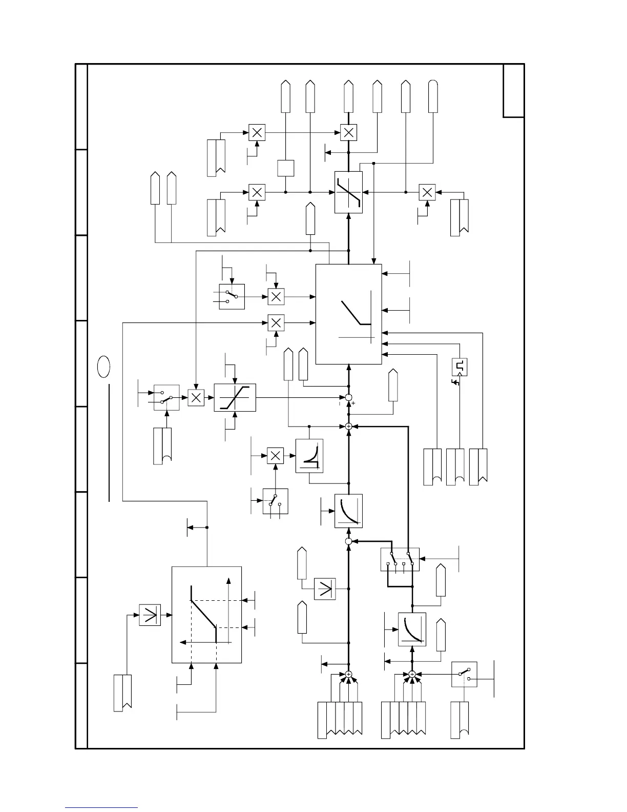
Sheet B170 Technology controller
87564321
1
0
0
1
0%
0%
-
+
0,10...30,00
10
10
0%
Y2
Y1
Y
X1 X2 X
Y
X
Kp Tn
x
y
1
0
1
1000
1
1000
.01
.02
.03
.04
.01
.02
.03
.04
10
-1
*
- B170 -
114
<1>
<1>
[B170.8]
[B170.7]
U490.F
(0,00)
U480 (0)
K
K
K
K
U484 (0)
K
K
K
K
K9243
n017
U487.F(0,00)
K9244
U489 (0)
K
U492.F
(1,00)
U493.F
(1,00)
U491.F
(100,00)
U482.F(0,000)
U483.F(0)
U497.F(0,0)
U498.F
(100,00)
U499.F
(-100,00)
K9242
K9246
U494.F
(3,000)
U488.F
(3,00)
U495.F(0)
U505 (0)
K
K9247
K9248
U508.F
(100,0)
U507 (1)
K
U512.F
(100,0)
U511 (1)
K
K9252
U510.F
(100,0)
U509 (9252)
K
K9250
K9254
K9253
K9251
n019
n018
U500 (0)
B
U506 (0)
B
U486 (0)
B
U496 (0)
B
0,00...200,00%
B9499
n016
K9240 K9241
U481.F(0,00s)
0,10...30,00
U485.F (0,00)
U502.F (0)
U503.F (1) U504.F (1)
K9245
K9249
Kp-factor
0 = D component acts only in actual-value channel
1 = Normal PID controller: D component is applied for control deviation
Enable technology controller
P component
I component
technology controller
Setpoint
Actual value
Tresholds
Filter time [s]
Inject additional
setpoint
Droop injection
Kp adaptation
Set I component
D component
Setting value for I component
Filter time
Technology controller
Technology controller
output
Setpoint
0 = Reset P
component
0 = Reset I
component
Positive limit
Negative limit
Controller at
output limit
Kp-factors
Stop I component

 Loading...