Function diagrams 05.05
8-112 SIEMENS AG 6RX1700-0AD76
SIMOREG DC Master Operating Instructions
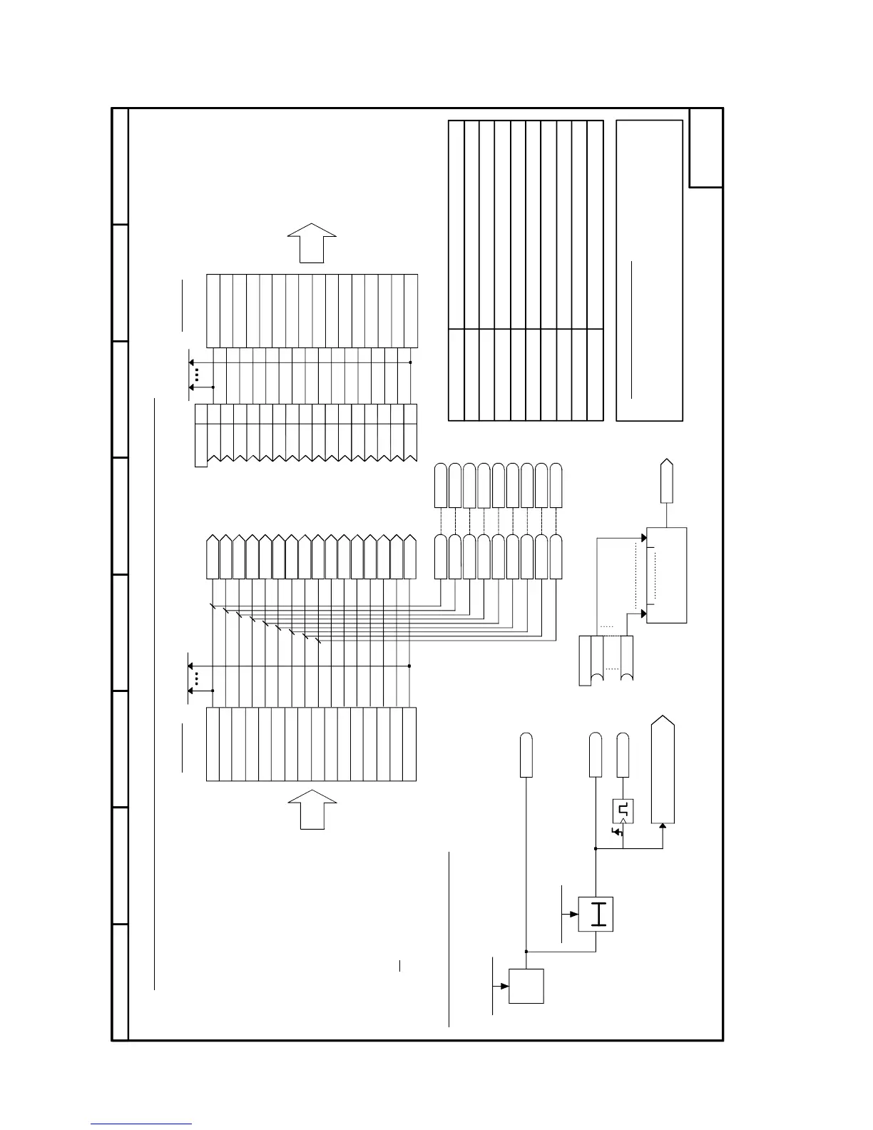
Sheet Z110 Data exchange with a technology board (TB) or
the 1
st
communications board (CB)
.04
.01
.03
.02
.06
.05
.07
.08
.10
.09
.14
.11
.13
.12
.16
.15
87564321
- Z110 -
<1>
<1>
T0
015
.01
.16
U728 (0)
B
B
K3020
[Z124.2]
[G182.6]
[G151.3]
[G183.6]
1s
B3030
B3031
K3001
K3002
K3003
K3004
K3005
K3006
K3007
K3008
K3009
K3010
K3011
K3012
K3013
K3014
K3015
K3016
B3100
Bit 0 ... Bit 15
B3200
B3300
B3400
B3500
B3600
B3700
B3800
B3900
B3115
B3215
B3315
B3415
B3515
B3615
B3715
B3815
B3915
U722.03 (0 ms)
U722.01 (0 ms)
B3035
K
K
K
K
K
K
K
K
K
K
K
K
K
K
K
K
32
167
0
33
0
0
0
0
0
0
0
0
0
0
0
0
U734
CB parameters 1 to 10
CB or TB diagnosis
CB parameter 11
1 = "Fault F082"
Initialize link to supplementary boards
Parameters for the 1
st
CB board
Message
monitoring time
Message monitoring for received process data:
Valid for the following configurations:
- CB only
- TB only
- CB after TB (CB in slot G)
- 2 CBs (for CB with the lower slot letter)
Bit 10 must be set in word 1 of the
receive data to ensure that the
process data are accepted as valid
data. Control word 1 must therefore
be transferred as the first PZD word.
(fault value 10)
Display parameter job (PKW) from CB
Display parameter response (PKW) to CB
Display parameter job (PKW) from TB
Display parameter response (PKW) to TB
Receive data
Word 1
Word 2
Word 3
Word 4
Word 5
Word 6
Word 7
Word 8
Word 9
Word 10
Transmit data
Fault message trigger
1 = "Telegram monitoring timeout"
Word 11
Word 12
Word 13
Word 14
Word 15
Word 16
Word 1
Word 2
Word 3
Word 4
Word 5
Word 6
Word 7
Word 8
Word 9
Word 10
Word 11
Word 12
Word 13
Word 14
Word 15
Word 16
every 16 bits
Data exchange with a technology board (TB) or the 1st communications board (CB)
from supplementary board
to supplementary board
n733.01 to .16
n735.01 to .16
Bus address
Enable parameterization
U711-U720 Index.01
n732 Index.01-.32
n738 Index.01-.04
n739 Index.01-.04
U721 Index.01-.05
P918 Index.01
n738 Index.09-.12
n739 Index.09-.12
U710 Index.01
P927
1 = "Fault delay timeout"
Fault delay time
When bit 10 ("control by PLC") = 0,
the other bits of word 1, as well as words
2 to 16 are
not written to connectors K3001 to K3016
or to binectors B3100 to 3915.
All these connectors and binectors retain their old values.
Binector / connector
converter
For transmission of double-word connectors see Section 7.7.10
See also connector type converter on sheet Z124
FS

 Loading...