05.05 Function descriptions
SIEMENS AG 6RX1700-0AD76 9-29
SIMOREG DC Master Operating Instructions
Brief start-up guide for 6RA70 converters
G-SST2
RS485
G-SST3
RS485
Select peer-to-peer protocol P790 = 5 P800 = 5
Baud rate P793 = 1 to 13 corresponding to 300 to 187500
baud
P803 = 1 to 13 corresponding to 300 to 187500
baud
No. of process data (PZD No.)
(applies to Receive and Send)
P791 = 1 to 5 P801 = 1 to 5
PZD assignment for control word
and setpoints
(received process data)
All received process data are taken to connectors
and must be wired up as required
All received process data are taken to connectors
and must be wired up as required
No. of PKW No parameters can be transferred No parameters can be transferred
PZD assignment for actual
values
(transmitted process data)
Selection of transmitted values via P794
(indices .01 to .05)
Selection of transmitted values via P804
(indices .01 to .05)
Telegram failure time P797 = 0.000 to 65.000s P807 = 0.000 to 65.000s
Bus termination P795 = 0: Bus term. OFF
1: Bus term. ON
(depending on type of link)
P805 = 0: Bus term. OFF
1: Bus term. ON
(depending on type of link)
2-wire / 4-wire transmission
via RS485 interface
"4-wire" operation is automatically selected "4-wire" operation is automatically selected
Cable Terminal assignments, see Section 6.8 or Sheet
G173 in Section 8
Terminal assignments, see Section 6.8 or Sheet
G174 in Section 8
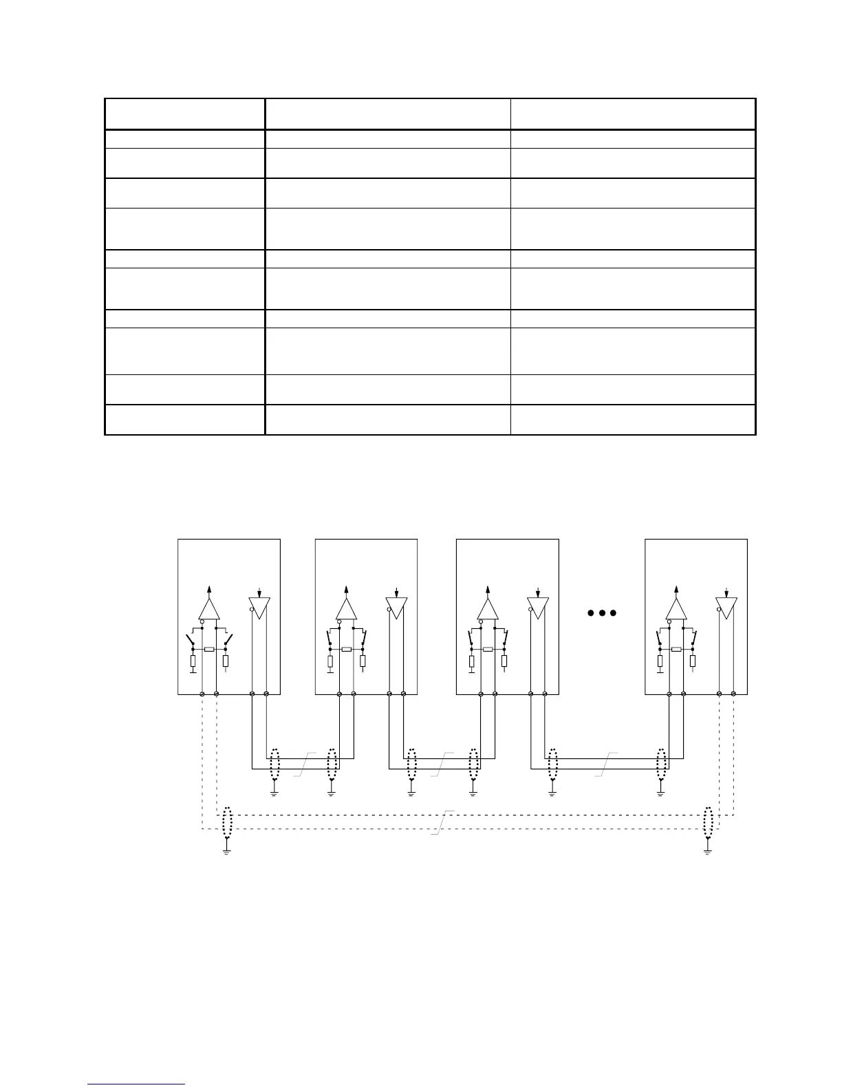
Examples of peer-to-peer links
Rx Tx
2)
+
56575859
--
++
6RA70
Rx Tx
+
56575859
--
++
6RA70
Rx Tx
+
56575859
--
++
6RA70
Rx Tx
+
56575859
--
++
6RA70
Peer link type "Series connection"
Each drive receives its own individual setpoint from the drive connected upstream (classic setpoint cascade)
1)
The interface cable shields must be connected directly on the converter with the lowest possible
impedance to converter or cubicle earth (e.g. via a clamp).
2)
Twisted cable, e.g. LIYCY 2x0.5 sqmm; with longer cables, an equipotential bonding conductor
must be used to ensure that the difference in frame potentials between nodes stays below 7 V.
3)
Optional data feedback loop via which drive 1 can monitor operation of the entire peer chain.
Drive 1
(Activate bus terminating
resistors when a data feed-
back loop is used)
Drive 2
(Bus terminating
resistors activated)
Drive 3
(Bus terminating
resistors activated)
Drive n
n=any number
(Bus terminating
resistors activated)
Data feedback loop 3)

 Loading...