SIMPRO-100
Control Equations & Relay Logic
B
PRIM-2400C 143
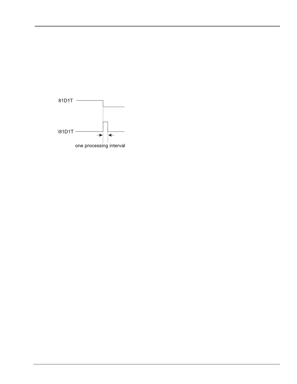
When frequency goes above the corresponding
pickup level 81D1P, Relay Word bit 81D1T
deasserts and an event report is generated (if the
relay is not already generating a report that
encompasses the new transition). This allows a
recovery from an underfrequency condition to be
observed. Figure B.2 demonstrates the action of
the falling-edge operator [\] on the
underfrequency element in setting ER.
Figure B.2 Result of Falling-Edge Operator on a
Deasserting Underfrequency Element
B.4.1.4 Control Equation Rising-Edge
Operator [/]
Use the rising-edge operator [/] with individual
Relay Word bits to cause a single
processing-cycle assertion when the Relay Word
bit changes state from logical 0 to logical 1. Do
not apply the [/] operator to groups of elements
within parentheses.
B.4.1.5 Control Equation Parentheses
Operator [( )]
Use parentheses to logically combine multiple
elements. More than one set of parentheses [( )]
can be used in a control equation setting.
Parentheses cannot be “nested” (parentheses
within parentheses) in a control equation setting.
For example, the following control equation
setting has two sets of parentheses:
Equation B.4
In the above example, the logic within the two
sets of parentheses is processed first and then
the two results are ANDed together. The example
equation could be used to provide simple motor
breaker failure protection.
B.4.1.6 Control Equation NOT
Operator [!]
Use the NOT operator [!] to invert a single Relay
Word bit and also to invert the result of multiple
elements combined within parentheses.
B.4.1.7 Set Control Equations Directly to
Logical 1 or Logical 0
To define a condition always picked up or always
dropped out, you can set control equations
directly to:
1 (logical 1) or 0 (logical 0)
If you set a control equation setting directly to 1, it
is always asserted/on/enabled. If you set a
control equation setting equal to 0, it is always
deasserted/off/disabled.
B.4.2 All Control Equations Must
Be Set
If you use control equations, every one needs to
be set by making it equal to one of the following:
• A single Relay Word bit
• A logical combination of Relay Word bits
• Directly to logical 1
• Directly to logical 0
If you are satisfied with the factory default logic
setting, you may leave the control equation
setting unedited.
SV4 = (SV4 + IN2 + TRIP) • (50PIT + 50N1T)