2
Installation
SIMPRO-100
28 PRIM-2400C
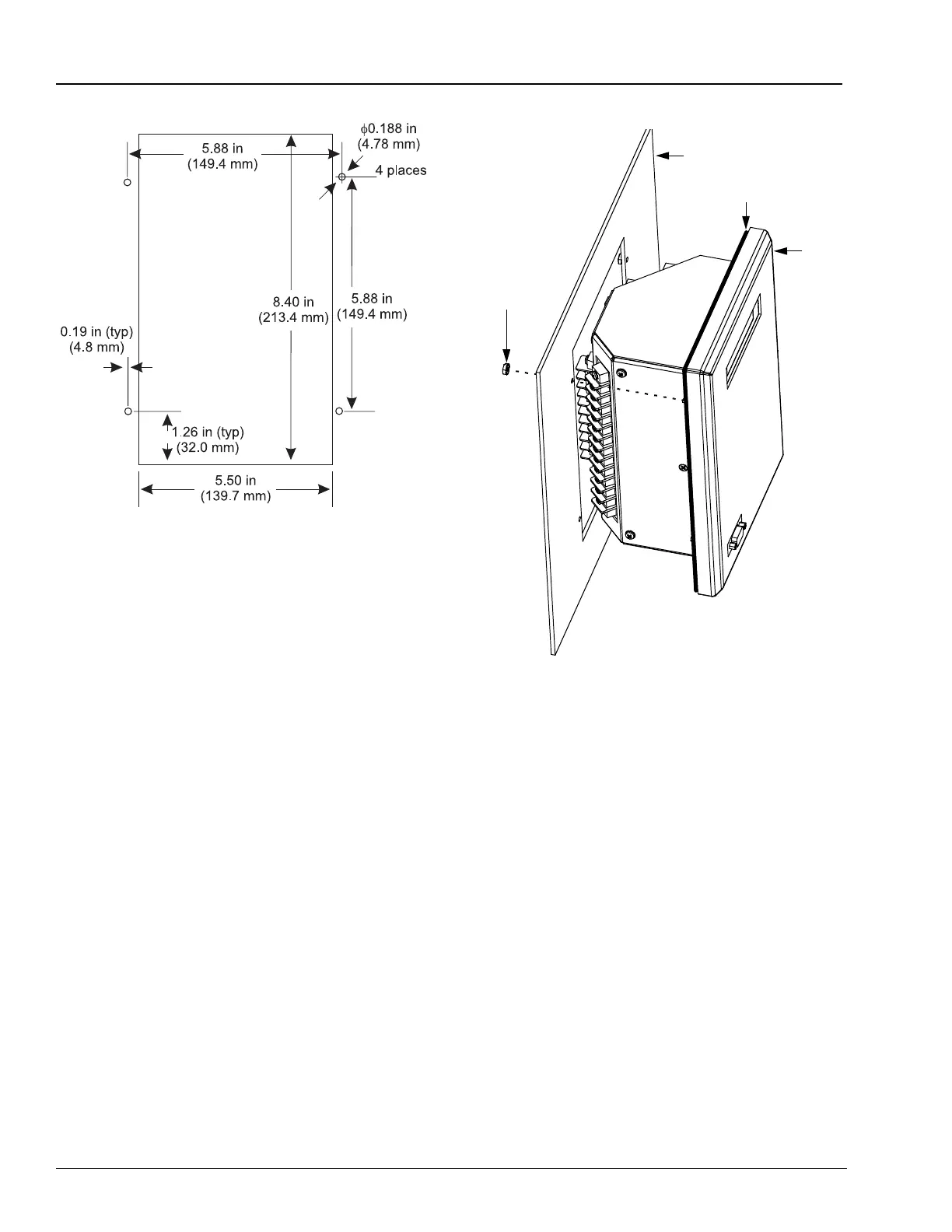
Figure 2.2 SIMPRO-100 Relay Cut and Drill
Dimensions
2.2 Relay Mounting
Mount the relay in the prepared panel cutout
using the four mounting studs and the locknuts
provided. Tighten the four nuts until snug
(10 – 15 in/lb torque); be careful not to
overtighten. Tightening these nuts causes the
rubber weather seal to compress in the channel,
pressing against the panel and sealing the cutout.
After mounting the relay, you may remove the
protective film that covers the rear panel. This
film is meant to protect the relay finish during
installation and is not required by the relay in
operation.
Figure 2.3 SIMPRO-100 Relay Panel Mounting
Detail
2.3 Relay Rear-Panel
Diagram
All relay electrical connections, except the
front-panel EIA-232 connections, are made at the
relay rear-panel, shown in Figure 2.4, page 29.
The relay rear panel is designed with two 45°
sections illustrated in Figure 2.1, page 27. These
cutaway areas provide additional clearance for
swing-panel mounting. The relay sides include
drawings that indicate the factory default function
of each relay terminal and typical wiring
diagrams.
Mounting Panel
Weather Gasket
Relay
6-32
Self-Locking Nut
(4 places)