B
Control Equations & Relay Logic
SIMPRO-100
146 PRIM-2400C
B.6 Front-Panel Display
Message
Configuration
There are four text display messages available in
the SIMPRO-100 Relay. Each text display has
two complementary screens.
Control equation display message setting DMn
(n = 1 – 4) controls the display of corresponding,
complementary text settings.
Example:
Message DM2_1 is displayed when the
control equation
DM2 = logical 1
Message DM2_0 is displayed when the
control equation
DM2 = logical 0
Make each text setting through the front panel or
serial port using the SET command. View text
settings using the serial port command SHOW.
These text settings are displayed on the relay
front-panel display on a two-second rotation.
The factory default settings display two
relay-identifying messages continuously and a
warning message in the event of an RTD failure.
B.7 Nondedicated
Control Equation
Variable Settings
The SIMPRO-100 Relay is equipped with four
nondedicated control equation variables. Each
variable has a defining control equation, a
time-delay pickup timer, and a time-delay dropout
timer.
The SV1 control equation is the logical definition
of the SV1 Relay Word bit. Make the control
equation setting by combining Relay Word bits
and logical operators.
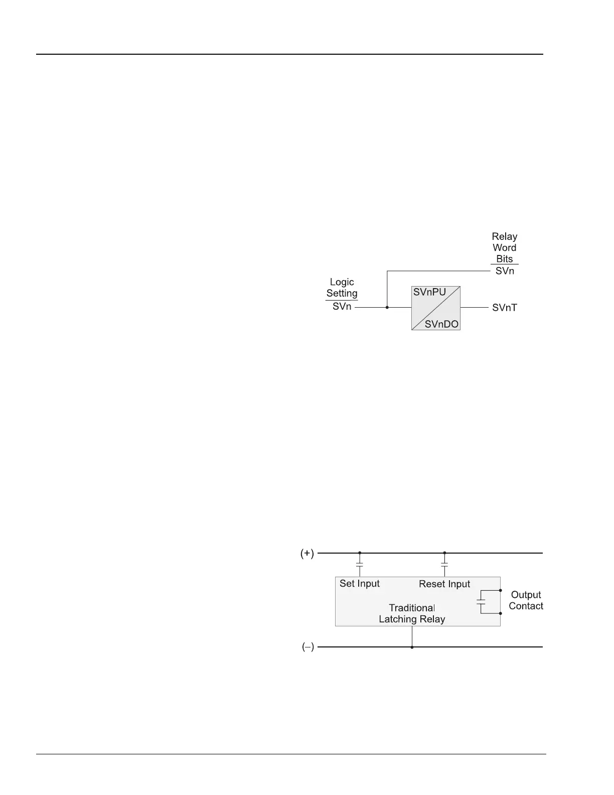
The SV1PU setting defines the SV1T Relay Word
bit time-delay pickup time. SV1T asserts SV1PU
seconds after the SV1 control equation result
becomes a logical 1. The SV1DO setting defines
the SV1T Relay Word bit time-delay dropout time.
Once SV1T is asserted, it remains asserted for
SV1DO seconds after the SV1 control equation
result becomes a logical 0. Figure B.4 illustrates
the control equation variable timer logic. For an
example control equation see Equation B.4.
Settings SV2 – SV4 operate similarly.
Figure B.4 Control Equation Variable Timer Logic
B.8 Latch Control
Switch Settings
The latch control switch feature of the
SIMPRO-100 Relay replaces latching relays. The
state of a traditional latching relay output contact
is changed by pulsing the latching relay inputs
(Figure B.5). Pulse the set input to close (set) the
latching relay output contact. Pulse the reset
input to open (reset) the latching relay output
contact.
Figure B.5 Traditional Latching Relay