SIMPRO-100
Installation
2
PRIM-2400C 35
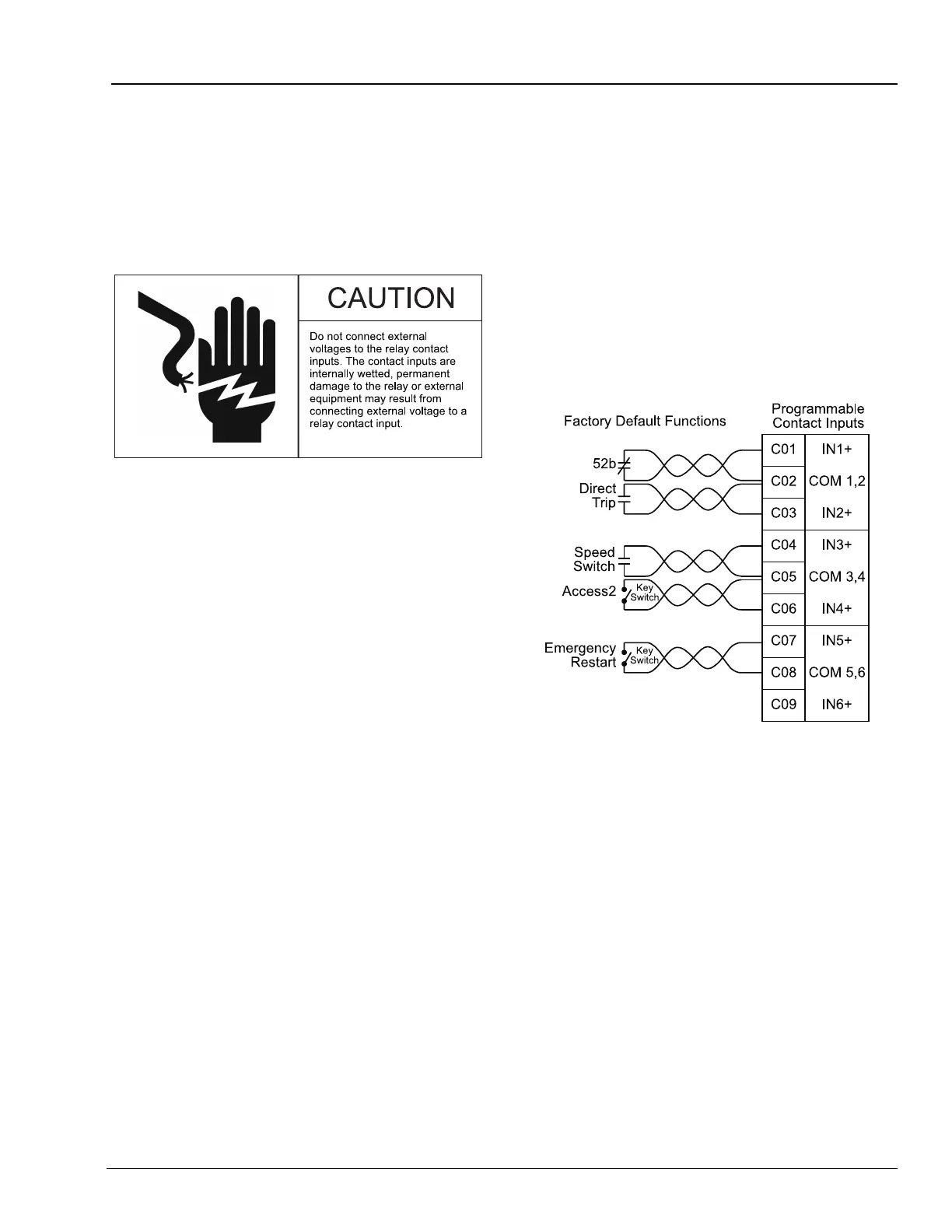
2.4.6 Contact Inputs
The SIMPRO-100 Relay is equipped with six
internally wetted contact inputs. The relay
supplies 28 Vdc wetting voltage for each input so
you only need to connect a dry contact, switch, or
jumper to the input.
The contact input functions are fully
programmable using the relay settings described
in Appendix B, page 137. For many applications,
the factory default configuration shown in
Figure 2.14 and described below will provide the
desired performance.
• Input IN1 is configured to monitor the motor
breaker or contactor 52B contact, if available.
• Input IN2 is configured for direct tripping.
When the contact connected to IN2 closes,
the relay will trip to shut down the motor.
• Input IN3 is configured for a speed switch. If
you want speed switch tripping, connect the
speed switch contact to IN3 or to the contact
input on the SIMPRO-100-RTD module. See
“Speed Switch Tripping”, page 58 for
additional information.
• Input IN4 is configured for Access Level 2
control. You can connect a key switch to this
input. When the switch contact is closed, you
can use relay Access Level 2 commands to
change relay settings or control output
contacts.
Note: The relay does not require that this
input be used for Level 2 access. You
can also enter the appropriate relay
password using the serial port or front
panel to gain entry to Access Level 2.
Shorting the IN4 input makes
password entry unnecessary; this is
useful if the Access Level 2 password
is lost.
• Input IN5 is configured to enable an
emergency restart. The Emergency Restart
function resets the relay thermal model and
overrides all other starting lockout functions to
allow an immediate motor start.
• Input IN6 is not applied in the factory default
settings.
Figure 2.14 Contact Input Factory Default Wiring
Diagram
2.4.7 Analog Output
The SIMPRO-100 Relay single analog output
provides a dc current level signal proportional to
any one of several relay measurements. Relay
settings, described in “Analog Output Settings”,
page 66, allow you to select the analog output
range (0 – 1 mA, 0 – 20 mA, or 4 – 20 mA).
Connect the relay output to the input of your PLC
or panel meter.
The maximum load for the analog output depends
on the selected output range. When you select
0 – 20 mA or 4 – 20 mA, the maximum load is
400 ohms. When you select 0 – 1 mA, the
maximum load is 8000 ohms.