SIMPRO-100
Installation
2
PRIM-2400C 33
operate in fail-safe mode, the relay holds the
contact in an energized position continuously,
then deenergizes the contact to trip. The contact
is also deenergized if the relay input power is
removed. The connections shown in Figure 2.11,
page 33 are suitable for use with a motor
contactor when trip fail-safe operation is desired.
When you set an output to operate in nonfail-safe
mode, the relay energizes the contact to trip. The
contacts do not change position when relay input
power is removed.
Note: When you select trip fail-safe operation,
the relay will automatically trip the motor
when input power is removed from the
relay or if the relay fails. This is desirable if
the protected motor is more valuable than
the process the motor supports. If the
process is more valuable than the motor,
disable trip fail-safe operation and make
appropriate wiring modifications. See
“Output Contact Fail-Safe, Trip Duration,
& Starting Lockout Settings”, page 67, for
additional information on fail-safe settings.
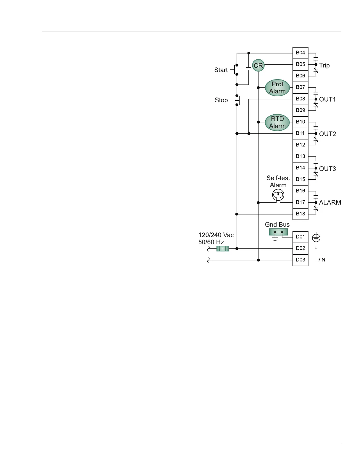
Figure 2.11 Contact Output Factory Default Wiring
Diagram