4
Settings Calculation
SIMPRO-100
44 PRIM-2400C
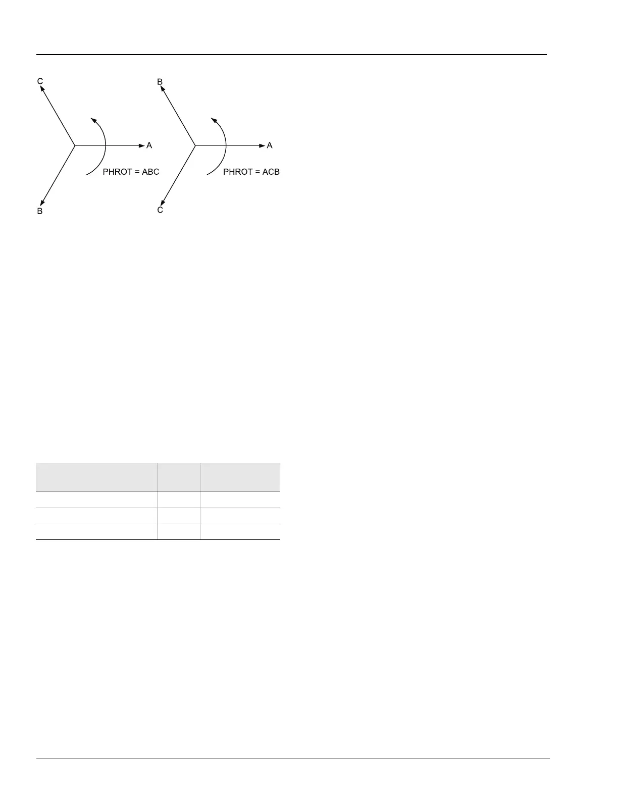
Figure 4.1 Phase Rotation Settings
Set the FNOM setting equal to your system
nominal frequency. The DATE_F setting allows
you to change the relay date presentation format
to either North American standard (Month/Day/
Year) or engineering standard (Year/Month/Day).
The DMTC setting defines the thermal time
constant used by the relay current and power
demand meter function, if voltages are included.
4.3.4 Voltage Transformer (VT)
Configuration Settings
(Relay Models
SIMPRO-100-R-V or N)
Table 4.5 VT Configuration Settings
These settings configure the optional relay
voltage inputs to correctly measure and scale the
voltage signals. Set the Phase VT Ratio (PTR)
setting equal to the VT ratio to:
Example: Phase VT Ratio Setting
Calculations
Consider a 4160 V motor application where
the phase-to-phase connected voltage
transformer ratios are 4160:118.
Set PTR = 4160/118 = 35.25 = 35
When phase-to-phase potentials are connected
to the relay, set DELTA_Y equal to D. When
phase-to-neutral potentials are connected to the
relay, set DELTA_Y equal to Y.
In applications where only a single voltage is
available, set SINGLEV equal to Y. As shown in
Figure 2.8 and Figure 2.9, page 31, the single
voltage must be connected to the A-phase input,
but it may be an A-N or an A-B voltage. Be sure
to set DELTA_Y equal to Y for an A-N input or
DELTA_Y equal to D for an A-B input voltage.
When you set SINGLEV equal to Y, the relay
performance changes in the following ways:
• Voltage Elements
When you use one phase-to-phase voltage,
the relay overvoltage and undervoltage
elements use the applied phase-to-phase
voltage only. When you use one
phase-to-neutral voltage, the relay voltage
elements use the applied phase-to-neutral
voltage only.
• Power Elements
When you use one voltage, the relay
assumes that the system voltages are
balanced in both magnitude and phase angle
to calculate apparent, real, and reactive
power and the power factor.
• Metering
When you use one phase-to-phase voltage,
the relay displays that magnitude and phase
angle. When you use one phase-to-neutral
voltage, the relay multiplies that magnitude by
the square-root of three to calculate an
approximate phase-to-phase voltage for
display. The relay also adjusts the phase
angle of the measured phase-to-neutral
voltage by ± 30º to represent phase-to-phase
voltage. The relay displays zero for the
magnitudes of the unmeasured voltages.
Balanced voltages are assumed for power
and power factor calculations.
Relays that are not equipped with phase voltage
inputs hide these settings and disable
voltage-based protection and metering functions.
Setting Prompt
Setting
Range
Setting Name =
Factory Default
Phase (VA, VB, VC) VT Ratio 1 – 6000 PTR = 100
Phase VT Connection D, Y DELTA_Y = Y
Single Voltage Input Y, N SINGLEV = N