
J
Joseph MosleyAug 5, 2025
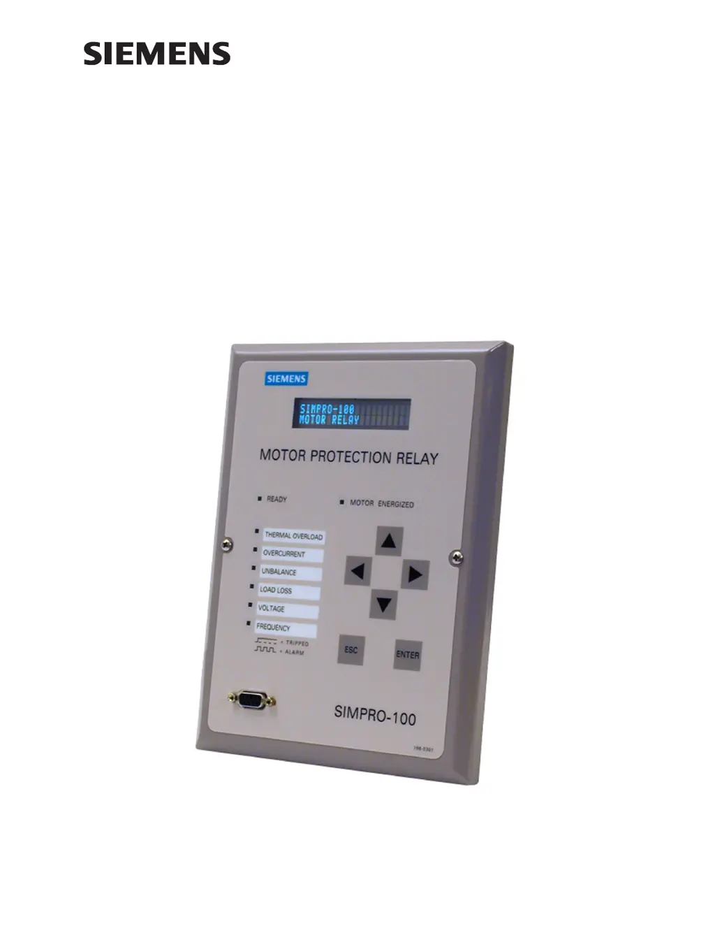
Why Siemens Relays do not respond to faults?
- Vvanessa88Aug 5, 2025
If a Siemens Relay doesn't respond to faults, it could be due to several reasons. First, check the relay settings to ensure they are properly configured. Second, verify the test source settings. Third, inspect the CT or PT input wiring for any errors. Finally, check the relay's self-test results using the front-panel Status of Relay function.


