SIMPRO-100
Motor Thermal Element
E
PRIM-2400C 207
Equation E.1
Heating factors K
1
and K
2
are defined by the
positive-sequence rotor resistance and
negative-sequence rotor resistance, respectively.
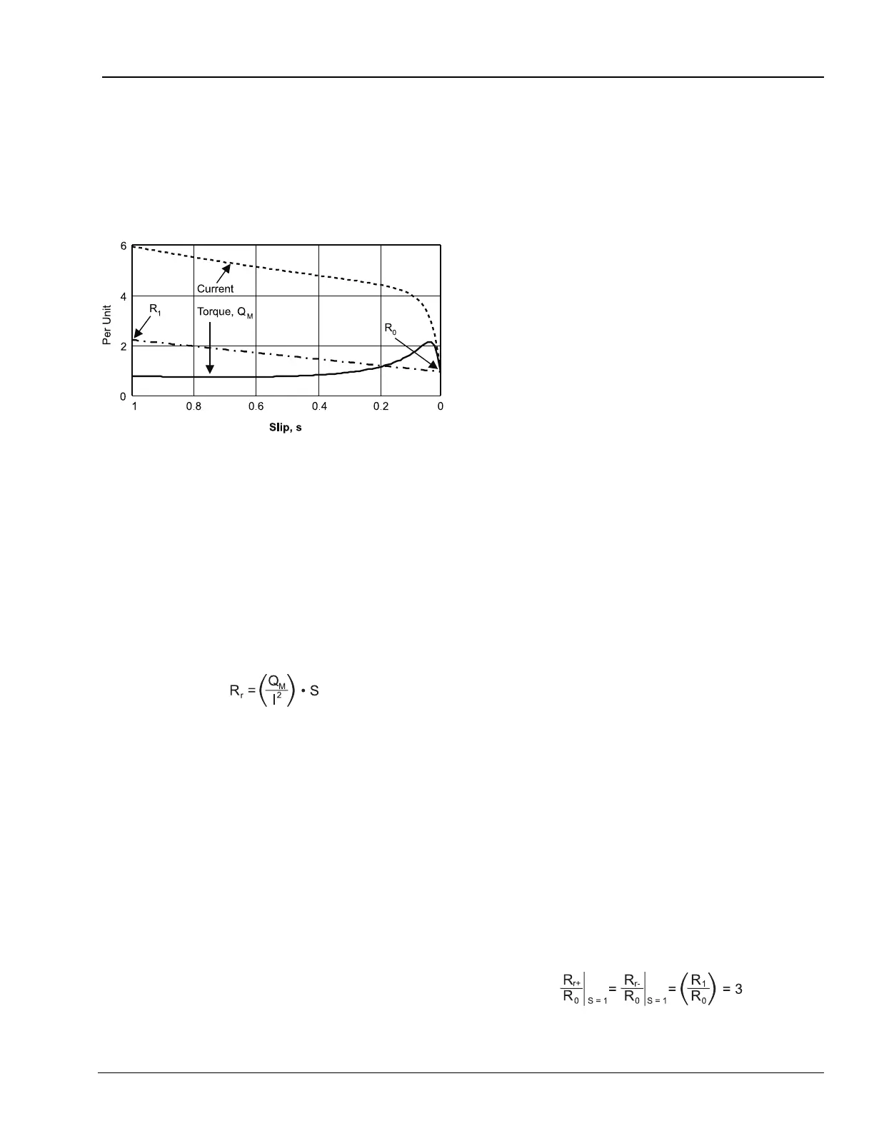
Figure E.3 Typical Induction Motor Current, Torque,
and Rotor Resistance versus Slip
Figure E.3 shows a plot of a typical induction
motor current, torque, and rotor resistance versus
slip. When motor slip is 1 per unit, rotor speed is
zero. As the motor approaches rated speed, slip
decreases to near zero.
Calculate the positive-sequence rotor resistance
plotted in Figure E.3 using Equation E.2.
Equation E.2
Where:
S=Motor slip
Q
m
= Motor torque at slip S
I = Motor positive-sequence current
at slip S
The positive-sequence rotor resistance is
represented as a linear function of slip S by
Equation E.3.
Equation E.3
Where:
R1 = Positive-sequence rotor
resistance at slip S = 1
R0 = Positive-sequence rotor
resistance at slip S = 0
To properly account for the heating effects of the
negative-sequence current, calculate the
negative-sequence rotor resistance. The rotor
has slip with respect to the stator
negative-sequence current. To determine the
value of the negative-sequence slip as a function
of positive-sequence slip S, observe that
negative-sequence stator currents cause
counter-rotating magnetic poles on the inside
face of the stator. When rotor speed is zero, the
counter-rotating poles induce fundamental
frequency currents in the rotor:
negative-sequence slip equals positive-sequence
slip S. When the rotor is spinning at near
synchronous speed, the counter-rotating
magnetic poles induce approximately
double-frequency currents in the rotor:
negative-sequence slip equals twice the
fundamental frequency.
Based on these observations, negative-sequence
slip equals (2 – S). Substituting this value for S in
Equation E.4, calculate negative-sequence rotor
resistance, R
r–
.
Equation E.4
Where:
R1 = Positive-sequence rotor
resistance at slip S = 1
R0 = Positive-sequence rotor
resistance at slip S = 0
To obtain factors expressing the relative heating
effect of positive- and negative-sequence current,
divide Equation E.3 and Equation E.4 by R
0
. For
the locked rotor case (slip S = 1).
Equation E.5
Heat Source = I
1
• K
1
+ I
2
• K
2
R
r+
= (R
1
– R
0
) • S + R
0
R
r-
= (R
1
– R
0
) • (2 – S) + R
0