SIMPRO-100
Motor Thermal Element
E
PRIM-2400C 209
E.5 Motor Running
Protection
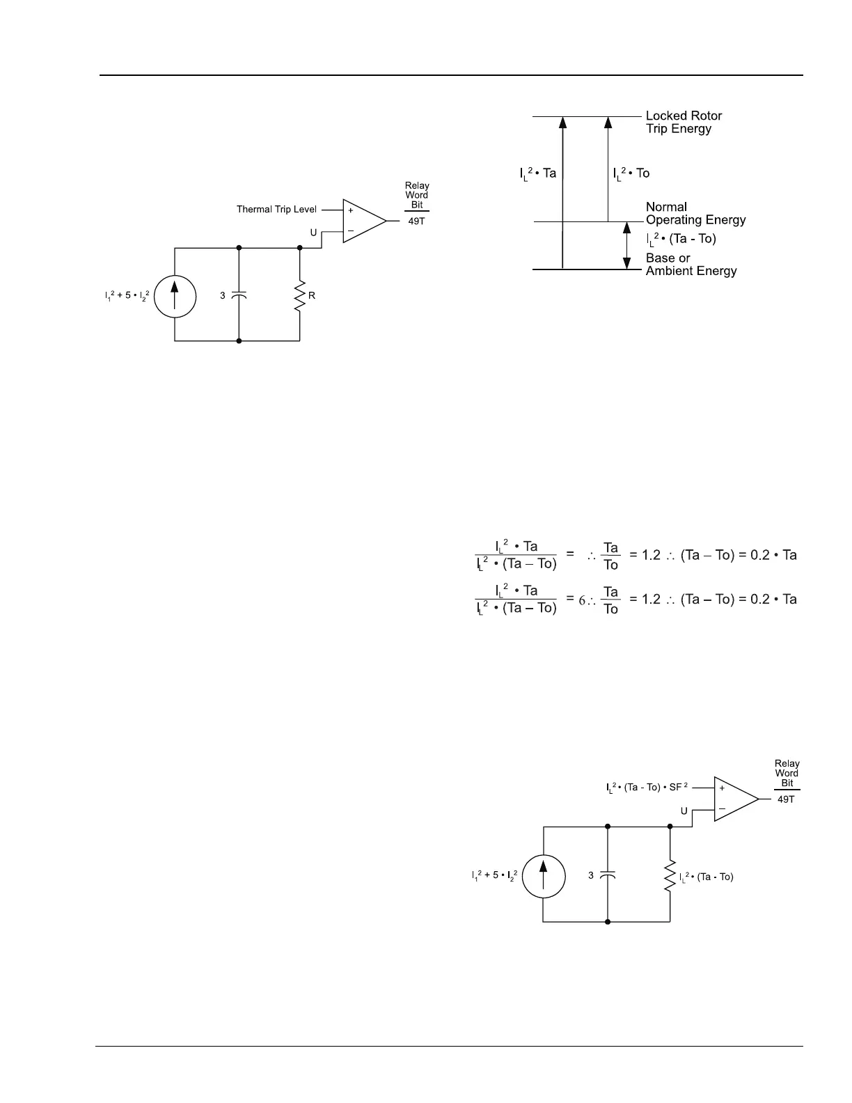
Figure E.5 Motor Running Thermal Element With
Resistance and Trip Level Undefined
When the motor is running, it returns heat energy
to its surroundings through radiation, conduction,
convection, and, in some cases, using forced
cooling. The motor running thermal element
provides a path for that energy return through the
resistor R, in Figure E.5.
To determine the value of that resistor, recall that
the motor will reach an energy level representing
its rated operating temperature when 1 per unit of
positive sequence current flows in the motor for a
long time. Since the positive-sequence heat
factor K
1
, is 1 in the running model, and 1 per unit
of I
1
squared equals 1, the value of resistor R
equals the energy level representing the motor
rated operating temperature.
To determine the normal operating energy, recall
that many motor datasheets publish two locked
rotor trip times:
• one longer time when the motor is started
from ambient temperature (referred to as Ta)
• one shorter time when the motor is started
from operating temperature (To)
Figure E.6 Calculating the Normal Operating Energy
Using Locked Rotor Trip Times
Figure E.6 shows a graphical representation of
the problem and its solution. The motor normal
operating energy is the difference between the
ambient and operating temperature locked rotor
times, multiplied by locked rotor current squared.
For those motors that do not publish separate
locked rotor times, assume that the locked rotor
trip energy is approximately six times the
operating energy in the relation.
Equation E.8
The motor ratings allow the motor to be run
continuously at the motor service factor, thus the
service factor SF, is accounted for in the running
thermal element trip threshold. Figure E.7 shows
the final running thermal element.
Figure E.7 Motor Running Thermal Element