SIMPRO-100
Settings Calculation
4
PRIM-2400C 47
time at six times full load current. For a cold
motor, the curve 10 trip time at six times full load
current is 25 seconds. Table 4.8, page 49 and
Table 4.9, page 49 show the cold motor thermal
limit time versus current for several curves.
Each increase in the curve number yields a
2.5 second increase in the hot motor thermal limit
time at six times full load current.
Continue calculating the balance of thermal
element settings with “Thermal Capacity Alarm
Setting”, page 53.
Example: Thermal Element Generic Method
Setting
A 4160 V, 800 HP motor is to be protected
using the SIMPRO-100 Relay Thermal
Element Generic Curve Method. The motor
data sheet includes the following
information.
Rated Horsepower (HP) = 800 HP
Rated Voltage (V) = 4160 V
Rated Full Load Current (A) = 101.0 A
Rated Locked Rotor Amps (A) = 620.4 A
Safe Stall Time, Hot = 30 seconds
Service Factor = 1.15
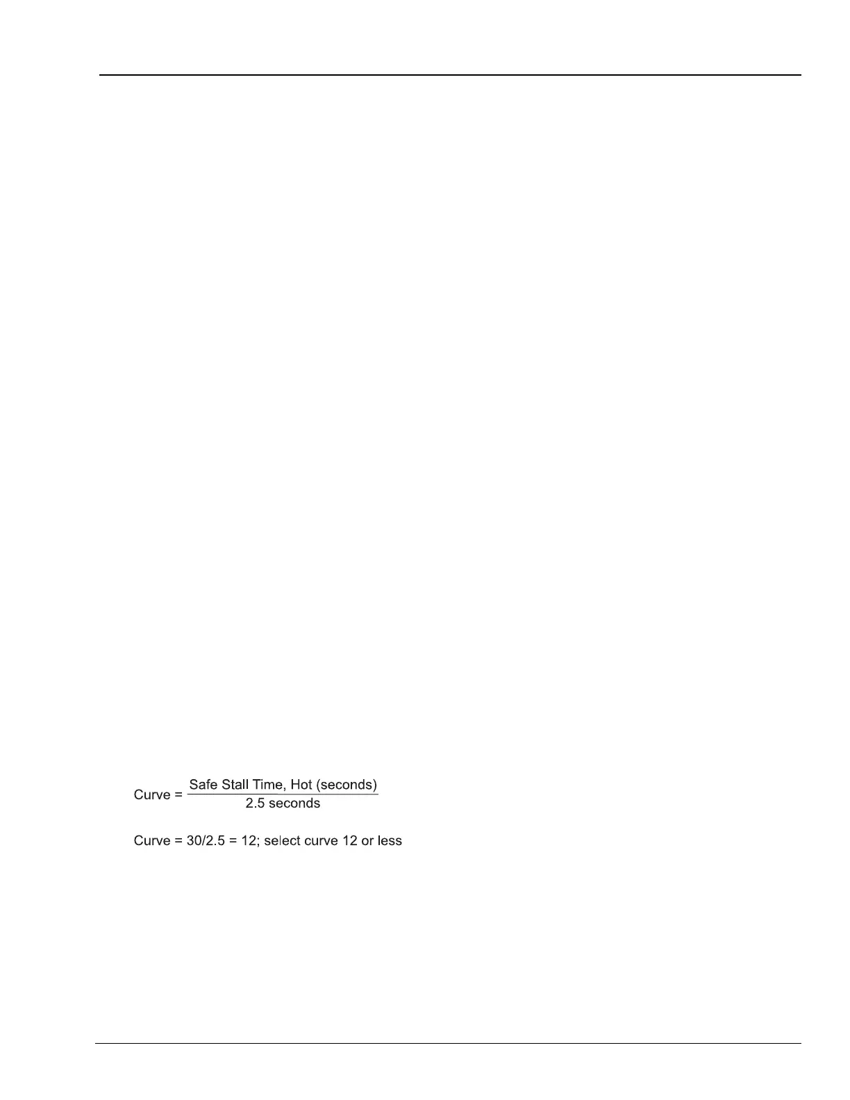
Each increase in generic curve number
increases the hot motor thermal limit time
by 2.5 seconds at six times full load current.
Therefore, we can select the maximum
curve number using the following equation.
Equation 4.1
Phase current transformers having 150:5
ratios are selected for the application. The
SIMPRO-100 Relay settings for the
application are shown below.
Current Transformer Ratio (CTR) =
150/5 = 30
CT Secondary Rating (ITAP) = 5
Full Load Amps (FLA) = 101/30 =
3.36 A secondary
Service Factor (SF) = 1.15
Curve Number (CURVE) = 12