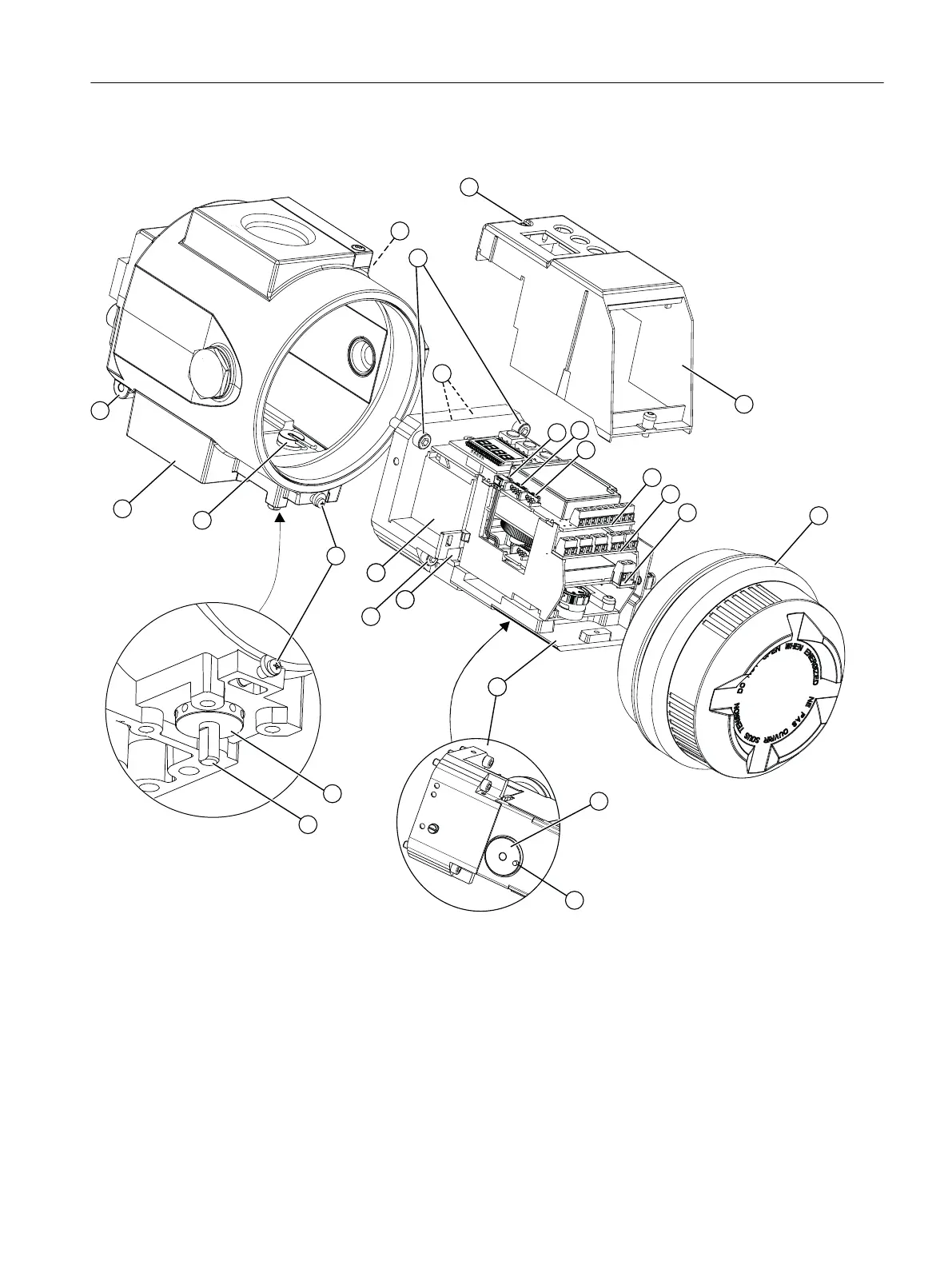
EasyManuals Logo

Siemens SIPART PS2 User Manual

Siemens SIPART PS2
372 pages
To Next Page IconTo Next Page
To Previous Page IconTo Previous Page
Page #57 background imageLoading...
Page #57 background image
Overview screen















Module cover Pneumatic block
Fixing screws module cover Warning label on the side opposite the nameplate
Fixing screws basic electronics Screw cap
Ribbon cable/connector for fitted potentiometer or external
position detection system
Feedback lever bracket with pin
Ribbon cable/connector for alarm module, SIA module or
mechanical limit switch module
Pin (feedback lever bracket)
Ribbon cable/connector for position feedback module Adjustment wheel for external friction clutch
Basic electronics Feedback shaft
Alarm module Fixing screws adapter
Installing/mounting
4.5 Installing the optional modules
SIPART PS2 with PROFIBUS PA
Operating Instructions, 05/2019, A5E00127926-AC 57

Table of Contents

Other manuals for Siemens SIPART PS2

Questions and Answers:

Question and Answer IconNeed help?

Do you have a question about the Siemens SIPART PS2 and is the answer not in the manual?

Siemens SIPART PS2 Specifications

General IconGeneral
Supply Pressure1.4 to 7 bar (20 to 100 psi)
Enclosure RatingIP66/NEMA 4X
Communication ProtocolsHART, PROFIBUS PA, FOUNDATION Fieldbus
Output Pressure0 to 100% of supply pressure
Hazardous Area CertificationATEX, IECEx, FM, CSA
TypeElectropneumatic
Input Signal4-20 mA
Rotation Angle30° to 90°
Operating Temperature-40°C to +80°C
MountingLinear and rotary actuators
Air ConsumptionTypically less than 0.1 kg/h

Related product manuals