⑨ Position feedback module Safety catch
⑩ Nameplate Clip
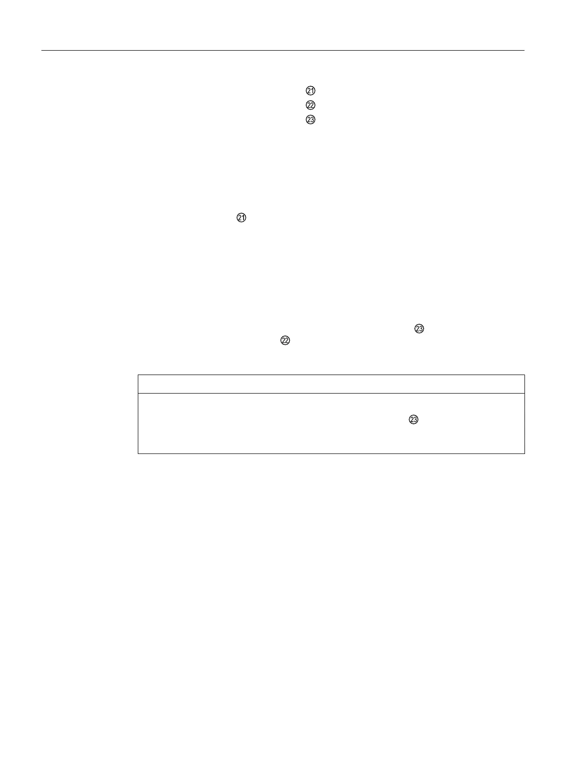
⑪ Adapter Enclosure
⑫ Transmission ratio selector
Figure 4-14 Installing the optional modules in the "flameproof enclosure" version
Opening the device version with "flameproof enclosure"
1. Disconnect the power supply lines or de-energize the power supply lines.
2. Open the safety catch .
3. Unscrew the screw cap ⑮.
4. Completely dismount the positioner from the actuator.
5. Turn the feedback shaft ⑲ on the positioner until the pin (feedback lever bracket) ⑰ below
the adapter ⑪ shows in the direction of removal. If you look into the enclosure below the
adapter, you will see the position of the pin.
6. Loosen the four fixing screws ⑳ of the adapter ⑪.
7. Completely remove the adapter ⑪ carefully from the enclosure .
The positioner comes with a clip and a pin (feedback lever bracket) ⑰ which interlock
and ensure backlash-free position feedback. To ensure backlash-free position feedback
make sure you remove the adapter ⑪ carefully.
NOTICE
Displaced O-rings
There are several O-rings between adapter ⑪ and enclosure . These O-rings may
come off during removal.
● Carefully remove the adapter. Make sure the O-rings do not get lost during removal.
8. Loosen the two fixing screws ② of the module cover ①.
9. Remove the module cover ①.
If you install an option module, proceed as described for the respective option module. Remove
the basic electronics with an internal NCS module.
If you replace the basic electronics or a pneumatic block, proceed as described in the
respective chapters under "Service and maintenance (Page 241)".
Installing/mounting
4.5 Installing the optional modules
SIPART PS2 with PROFIBUS PA
58 Operating Instructions, 05/2019, A5E00127926-AC
 Loading...


