Devices without flameproof enclosure are:
● Normal version of devices
● Intrinsically safe versions
● Versions for zones 2 and 22
Procedure for device versions without flameproof enclosure
-
8
7
82
6
81
10
9
Binary
input 1
+
24V
33
Positioner
Transmission ratio selector
Shut
Down
input
BUS
Shut Down
disabled
90
O
O
Jumper
Shut Down
enabled
r
r
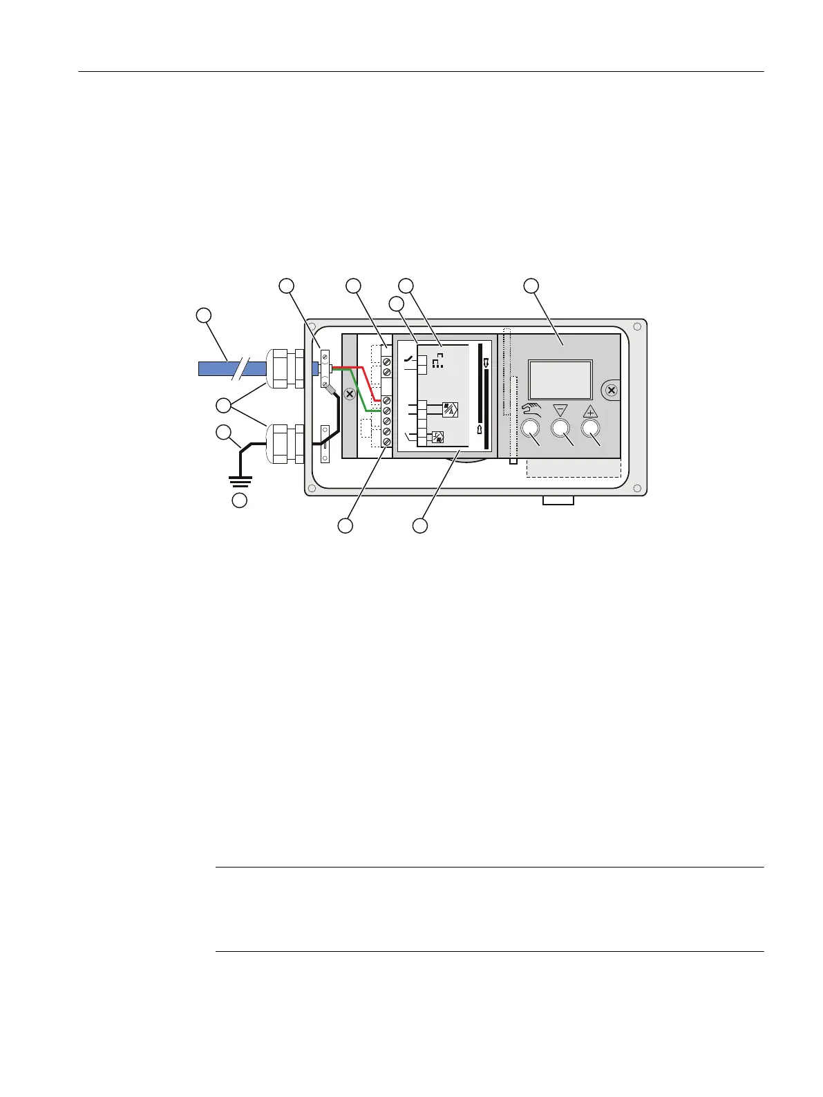
① Bus cable ② Cable clamp
③ Basic electronics ④ Wiring diagram on module cover
⑤ Jumper on basic electronics ⑥ Module cover
⑦ Label ⑧ Terminal strip with screw-type terminals
⑨ Earth potential ⑩ Grounding cable
⑪ Cable glands
Figure 5-4 Connection of bus cable and grounding cable for device version with polycarbonate
enclosure
1. Strip the bus cable ①.
2. Open the enclosure of the positioner by unlatching the four cover screws.
3. Insert the prepared bus cable (described in Bus cable (Page 82)) through the cable inlet.
4. Fasten the shield using the clamp ② and the two screws on the enclosure.
5. Tighten the cable inlet.
6. Connect the red and the green wires to terminals 6 and 7 of the basic electronics as shown
in the following picture. The polarity does not play any role here.
Note
Bus cable and grounding cable for device version with stainless steel/aluminum enclosure
In the case of the stainless steel or aluminum enclosure, use the grounding terminal
provided on the outside of the device.
Connect
5.2 Electrical wiring
SIPART PS2 with PROFIBUS PA
Operating Instructions, 05/2019, A5E00127926-AC 83
 Loading...


