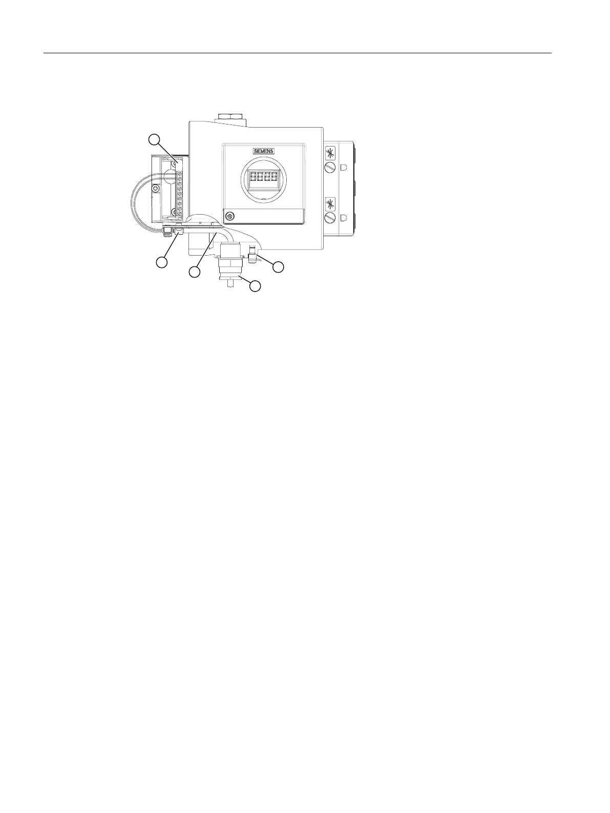
Procedure for device versions with flameproof enclosure "Ex d"
① Basic electronics bus cable
② Grounding terminal
③ Ex d certified cable inlet
④ Bus cable
⑤ Cable clamp/shield
Figure 5-5 Connection of bus cable for versions with flameproof enclosure
1. Strip the bus cable.
2. Open the safety catch and unscrew the screw cap to open the positioner.
3. Insert the prepared bus cable ④ (described in Bus cable (Page 82)) through the Ex d-
certified cable inlet ③. Follow the corresponding guidelines if you are using a conduit piping
system.
4. Fasten the shield on the adapter using the clamp ⑤ and the two screws.
5. Tighten the Ex d-certified cable inlet ③.
6. Connect the red and the green wires to terminals 6 and 7 of the basic electronics as shown
in the following picture. The polarity does not play any role here.
If a bus connection is not present, connect a separate power source with the following values
to terminals 6/7:
● With intrinsically-safe devices: intrinsically-safe isolating power supply with 24 V DC
● With non-intrinsically-safe devices: 15 to 30 V DC
Then match the positioner to the respective actuator by configuring and initializing it. Finally set
the bus address.
Connect
5.2 Electrical wiring
SIPART PS2 with PROFIBUS PA
84 Operating Instructions, 05/2019, A5E00127926-AC

 Loading...


