Measured Voltage Circuits, Synchronization Function
With regard to the synchronization function, the control of the voltage transformer via the primary switch
through is an imperative test to be carried out.
The tests can differ depending on the arrangement of the voltage transformer. The following examples
contain the example of condition and describe typical applications. More tests have to be autonomously
decided.
If the generator, for example, is not yet ready for operation, the preliminary test can be executed with the
system voltage. Here if necessary, the starpoint of the generator has to open.
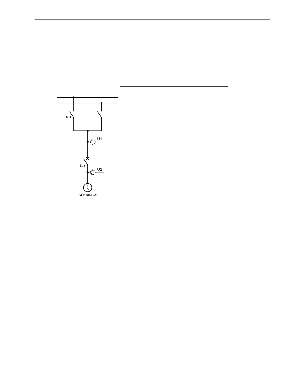
If the synchronizers have via the
Voltage Transformers at both sides of the circuit breaker (see the following
figure), in this way the voltage transformers can be simply executed to the voltage check:
[messspg-zur-sync-280203-oz, 1, en_GB]
Figure 3-20 Measuring voltages for synchronization
Checking with Side Connection Voltage Transformer
With open circuit breaker (b) , the busbar voltage transformer from the system is set under voltage: Isolator (a)
CLOSE.
With the 7VE61 and 7VE63 the voltage for the operational measured values is read out as voltage U1 and
compared with the actual voltage.
For three-phase systems the phase sequence is checked. If each of the two phase-to-phase voltages or three
phase-to-earth voltages are connected to the device and the parameter 6113 PHASE SEQUENCE is set to
clockwise rotation (L1 L2 L3) or set to anti-clockwise rotation (L1 L3 L2), the phase sequence voltage can
be read out in the operational measured values. If there is no conformity with the parameterized phase
sequence voltage, the corresponding annunciations are indicated. Thus, the secondary wiring mode to the
device is checked. If monophase systems or two phase-to-phase voltages are not connected , the parameter
6113 PHASE SEQUENCE is set to NO.
Busbar - Line Isolator Open (a)
After starting up the generator, the generator voltage is read out in the operational measured values as
voltage U2 and compared with the actual voltage. It has to be taken into consideration that the operational
measured value of the voltage U2 is influenced by the adaptation factor 6121 Balancing U1/U2. Normally,
however, this factor is set to 1 and if necessary, first when the checking of the secondary voltage circuits is
finished, the deviating values can be set.
Now, with three-phase systems the phase rotation check is executed with the generator voltage: The phase
rotation of the generator voltage must be equal to the phase rotation of the system voltage. In this case the
phase rotation can be read out in the operational measured values. If there is no conformity with the parame-
Mounting and Commissioning
3.3 Commissioning
SIPROTEC 4, 7VE61 and 7VE63, Manual 177
C53000-G1176-C163-3, Edition 10.2017

 Loading...


