By reading the operational measured values one should check that within the framework of the measuring
tolerances
•
Both voltages U1 and U2 are equal
•
Both frequencies f1 and f2 are equal.
If the secondary voltages are not equal due to different voltage transformer, an appropriate correction can be
performed with the help of the adaptation factor 6121 Balancing U1/U2.
In the operational measured values of the 7VE61 and 7VE63 one should check also that within the framework
of the measuring tolerances
•
The difference voltage dU is zero
•
The difference frequency df is zero
•
The difference angle dα is zero.
If for three-phase systems from the 7VE61 and 7VE63 the phase rotation checks are executed, the same phase
rotation has to be displayed for both voltages in the operational measured values.
With multiple busbars, the attempt for each busbar voltage has to be checked.
In case of several synchronizing points, each of the synchronizing points has to be tested.
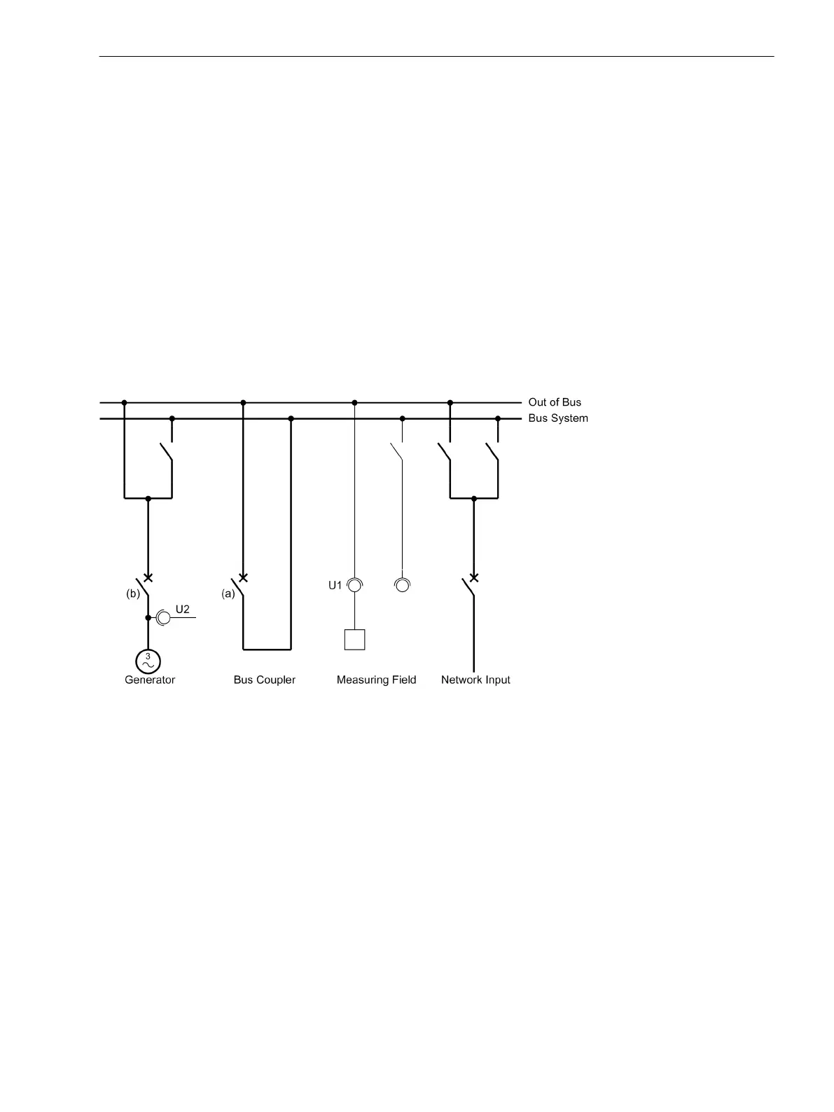
[ueberpruefung-messspg-im-messfeld-beispiel1-280203-oz, 1, en_GB]
Figure 3-21 Testing the measuring voltages in the measuring field — Example 1
Synchronization of Networks
The previous rules apply for the synchronization of systems. The following figure shows a possible switching
arrangement. Identical tests are executed as for the “checking with busbar voltage transformer”. For details,
see above.
Mounting and Commissioning
3.3 Commissioning
SIPROTEC 4, 7VE61 and 7VE63, Manual 179
C53000-G1176-C163-3, Edition 10.2017

 Loading...


