[messspg-synchronisation-ueber-trafo-170403-kn, 1, en_GB]
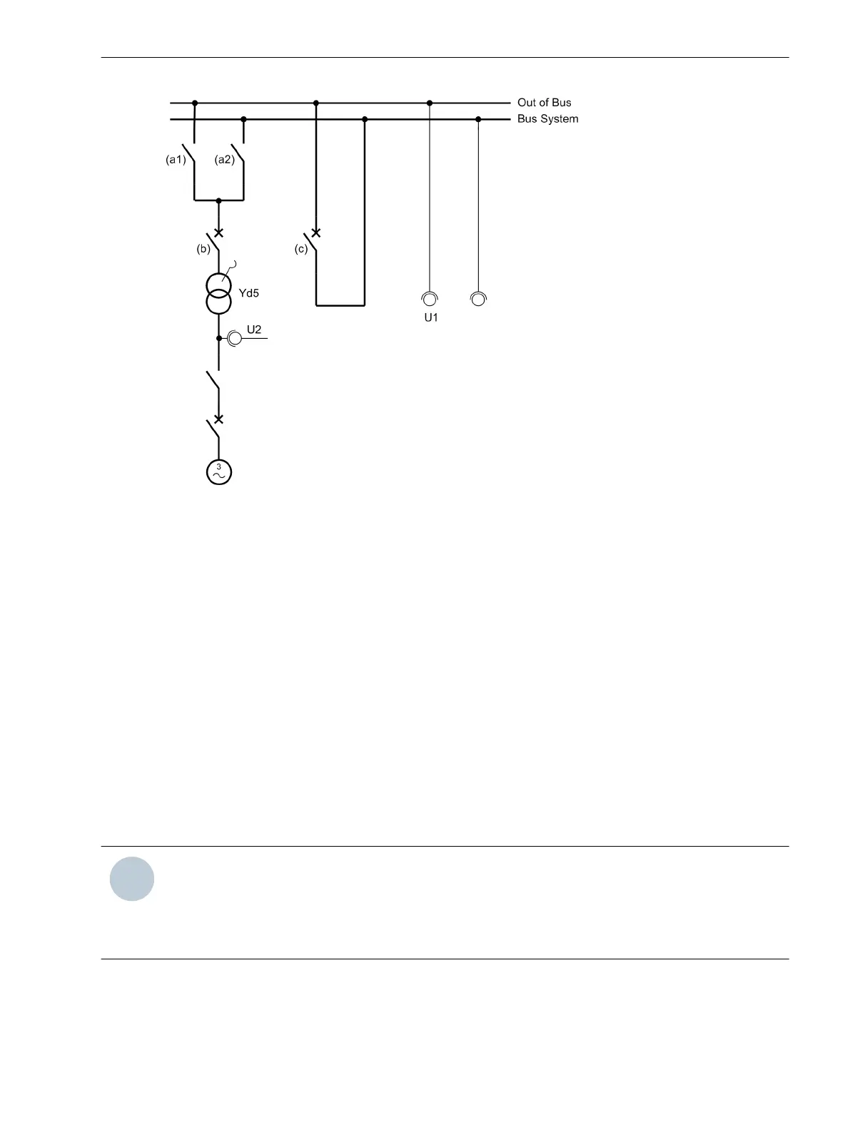
Figure 3-23
Measuring voltages with synchronization via the transformer
The following checking steps have to be executed analogically to the previous checkings:
•
Set the tap changer of the transformator to the nominal position
•
Circuit breaker (b) is open and section switch (c) closed
•
Check the measured values on side U1 (U1, f1, phase rotation)
•
Check that the transformer differential protection is ready for operation
•
Close isolator (a1) and then close the circuit breaker (b)
•
Check the measured values on side U2 (U1, f1, phase rotation)
•
Compared the measured values on side 1 and on side 2:
– Voltage equality U1 = U2
– Frequency equality f1 = f2
– The difference voltage dU is zero
– The difference frequency df is zero
– The difference angle dα is zero
NOTE
If dU and dα are unequal to zero, then wiring or setting error exist.
– Activate the tap changer and check again the measured values. The measured values on the side 2 have
to remain the same and all differential quantities must be equal to zero.
– After the test has been completed, you can reestablish the output switching condition.
Mounting and Commissioning
3.3 Commissioning
SIPROTEC 4, 7VE61 and 7VE63, Manual 181
C53000-G1176-C163-3, Edition 10.2017

 Loading...


