[logik-schalten-auf-spannungslose-ss-140403-kn, 1, en_GB]
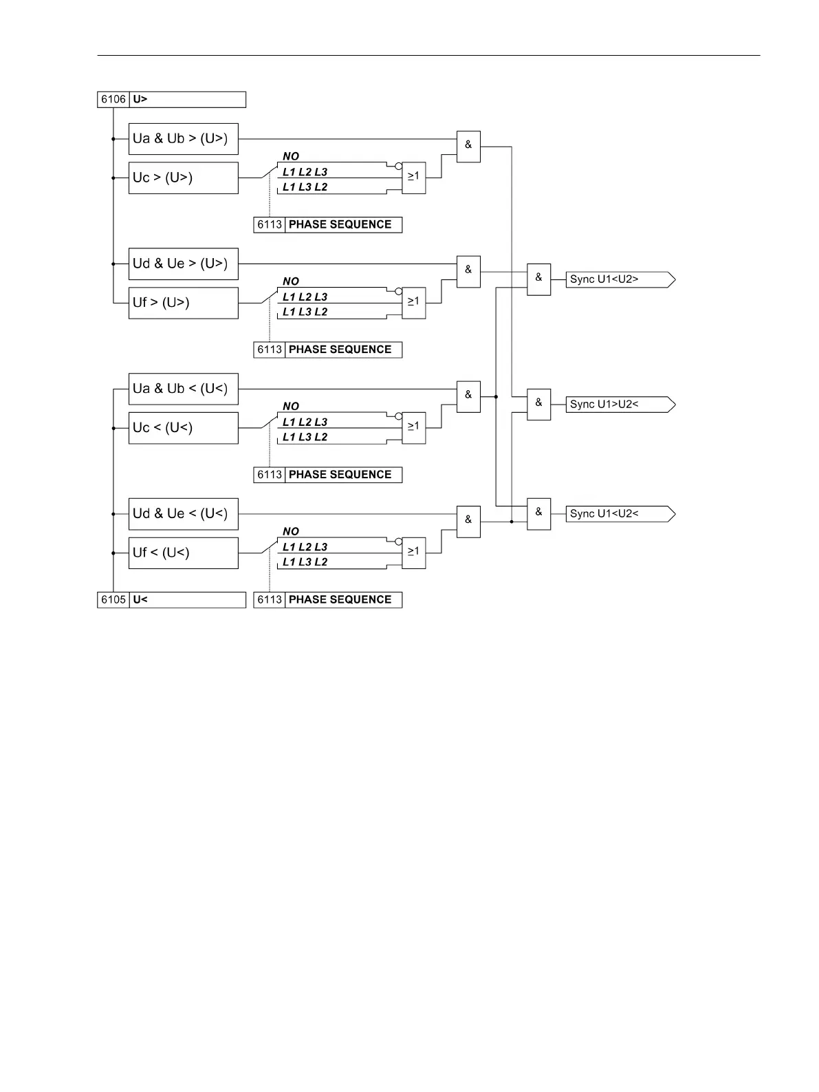
Figure 2-12
Logic diagram: Connection to dead line/bus with three-phase synchrocheck
The close check condition required can be indicated to the device by setting parameter. Alternatively it is also
possible to activate the corresponding condition via binary input. The associated logic is shown in Figure 2-13.
The logic diagram does not show that the voltage transformer protection switch is also scanned. If this is
active, in principle no enabling is allocated. It is therefore obligatory to configure this (see Connection exam-
ples in the Appendix).
Functions
2.2 Paralleling Functions
SIPROTEC 4, 7VE61 and 7VE63, Manual 47
C53000-G1176-C163-3, Edition 10.2017

 Loading...


