[df-dt-frequenzaenderung-020827-ho, 1, en_GB]
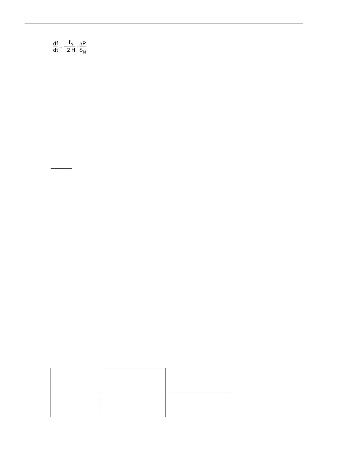
Where are:
f
N
Nominal Frequency
ΔP Active power change
ΔP = P
Consumption
– P
Generation
S
N
Nominal apparent power of the machines
H Inertia constant
Typical values for H are:
for hydro-electric generators (salient-pole machines) H = 1.5 s bis 6 s
for turbine-driven generators (cylindrical-rotor machines) H = 2 s bis 10 s
for industrial turbine-generators H = 3 s bis 4 s
Example:
f
N
= 50 Hz
H = 3 s
Fall 1: ΔP/S
N
= 0.12
Fall 2: ΔP/S
N
= 0.48
Fall 1: df/dt = –1 Hz/s
Fall 2: df/dt = –4 Hz/s
The default settings are based on the above example. The four stages have been set symmetrically.
Time Delays
The delay time should be set to zero wherever the protection function is supposed to respond very quickly.
This will be the case with high setting values. For the monitoring of small changes (< 1Hz/s), on the other
hand, a small delay time can be useful to avoid overfunctioning. The delay time for stage 1 is set at address
4504 T df1/dt, and the time set there is added to the protection operating time.
Release by the Frequency Protection
The parameter df1/dt & f1 (Address 4505) is used to set the release of the stage from a certain frequency
threshold on. For this the pertinent frequency stage of the frequency protection is queried. In the setting
example this is stage f1. To exclude coupling of the two functions, the parameter can be set to OFF (default
setting).
Advanced Parameters
The advanced parameters allow setting each for two stages (e.g. df1/dt and df2/dt) the dropout difference and
the measuring window. This setting can only be done with the DIGSI communication software.
Einstellungsänderungen sind erforderlich, wenn man z.B. eine große Rückfalldifferenz haben möchte. Sollen
sehr kleine Frequenzänderungen (<0,5 Hz/s) erfasst werden, so sollte das voreingestellte Messfenster verlän-
gert werden. Damit verbessert man die Messgenauigkeit.
Setting value
Stage df
n
/dt
df/dt HYSTERESE
(Adr. 4519, 4521)
dfx/dt M-WINDOW
(Adr. 4520, 4522)
0.1...0.5 Hz/s ≈ 0.05 25...10
0.5...1 Hz/s ≈ 0.1 10...5
1...5 Hz/s ≈ 0.2 10...5
5...10 Hz/s ≈ 0.5 5...1
Functions
2.7 Rate-of-frequency-change protection
94 SIPROTEC 4, 7VE61 and 7VE63, Manual
C53000-G1176-C163-3, Edition 10.2017

 Loading...


