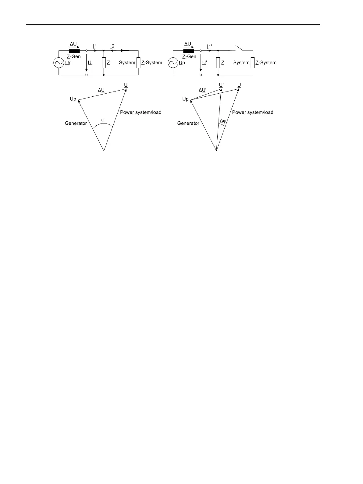
[spannungszeiger-nach-entlastung-020904-ho, 1, en_GB]
Figure 2-45 Voltage Vector Following Load Shedding
The function features a number of additional measures to avoid spurious tripping, such as:
•
Correction of steady-state deviations from rated frequency
•
Frequency operating range limited to f
N
± 3 Hz
•
Minimum voltage for enabling
•
Blocking on voltage connection or disconnection
Logic
The logic is shown in the following figure. The phase angle comparison determines the angle difference, and
compares it with the set value. If this value is exceeded, the vector jump is stored in a RS flip-flop. Trippings
can be delayed by the associated time delay.
The stored pickup can be reset via a binary input, or automatically by a timer (address 4604 T RESET).
The vector jump function becomes ineffective on exiting the admissible frequency band. The same applies for
the voltage. In such a case the limiting parameters are U MIN and U MAX.
If the frequency or voltage range is not maintained, the logic generates a logical 1, and the reset input is
continuously active. The result of the vector jump measurement is suppressed. If, for instance, the voltage is
connected, and the frequency range is correct, the logical 1 changes to 0. The timer T BLOCK with reset delay
keeps the reset input active for a certain time, thus preventing a pickup caused by the vector jump function.
If a short-circuit causes the voltage to drop abruptly to a low value, the reset input is immediately activated to
block the function. The vector jump function is thus prevented from causing a trip.
Functions
2.8 Jump of Voltage Vector
98 SIPROTEC 4, 7VE61 and 7VE63, Manual
C53000-G1176-C163-3, Edition 10.2017

 Loading...


