EasyManua.ls Logo

SKF MKU Series - Page 44

SKF MKU Series
102 pages
Print Icon
To Next Page IconTo Next Page
To Previous Page IconTo Previous Page
Loading...
44
Connections via:
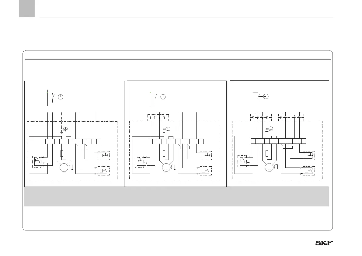
4.7.4 MKU, 2-liter reservoir, voltage design 24 VDC, with pushbutton
MKU, 2-liter reservoir, voltage design 24 VDC, with pushbutton, Fig. 14
2x cable glands
1x XS1 connector (DIN EN 175301-803 A)
1x cable gland
XS1 connector (DIN EN 175301-803 A)
XS2 plug (M12x1)
1) Optional See Chapter 4.6.1 for legend to the terminal diagrams
2) Optional: Contact closes at minimum level (NO)
MKU1-11B _ _ 2000+924MKU1-11B _ _ 1000+924
MKU1-11B _ _ 4000+924
MKU1-11B _ _ 0000+924
MKU1-11B _ _ 3000+924
L+
M
L+/S
PE
3 1 2
BU
BK
PE
BN
+24V DC PELV
DS Signal
WS Signal
1 4 2
BN
BK
WH
3
BU
BN
RD
1a
1
1b
BK
1 32 4 5 6
P
Q
87 9 1210 11
GY
GY
BK
BK
GNYE
1)
GY
RD
BK
1)
2)
24V DC
951-115-018
XS1
XS2
DK
DS
WS
X1
M
F
1 32 4 5 6
P
Q
GY
GY
BK
BK
87 9 1210 11
BN
RD
1a
1
1b
BK
1)
RD
BK
1)
2)
L+
M
L+/S
PE
3 1 2
BU
BK
PE
BN
+24V DC PELV
DS Signal
WS Signal
GNYE
24V DC
951-115-017
DS
WS
X1
DK
M
XS1
F
1 32 4 5 6
P
Q
GY
GY
BK
BK
87 9 1210 11
BN
RD
1a
1
1b
BK
1)
RD
BK
1)
2)
L+
M
L+/S
PE
24V DC
+24V DC PELV
DS Signal
WS Signal
GNYE
951-115-016
DS
WS
X1
DK
M
F
EN
4. Assembly

Table of Contents

Other manuals for SKF MKU Series

Related product manuals