47
4
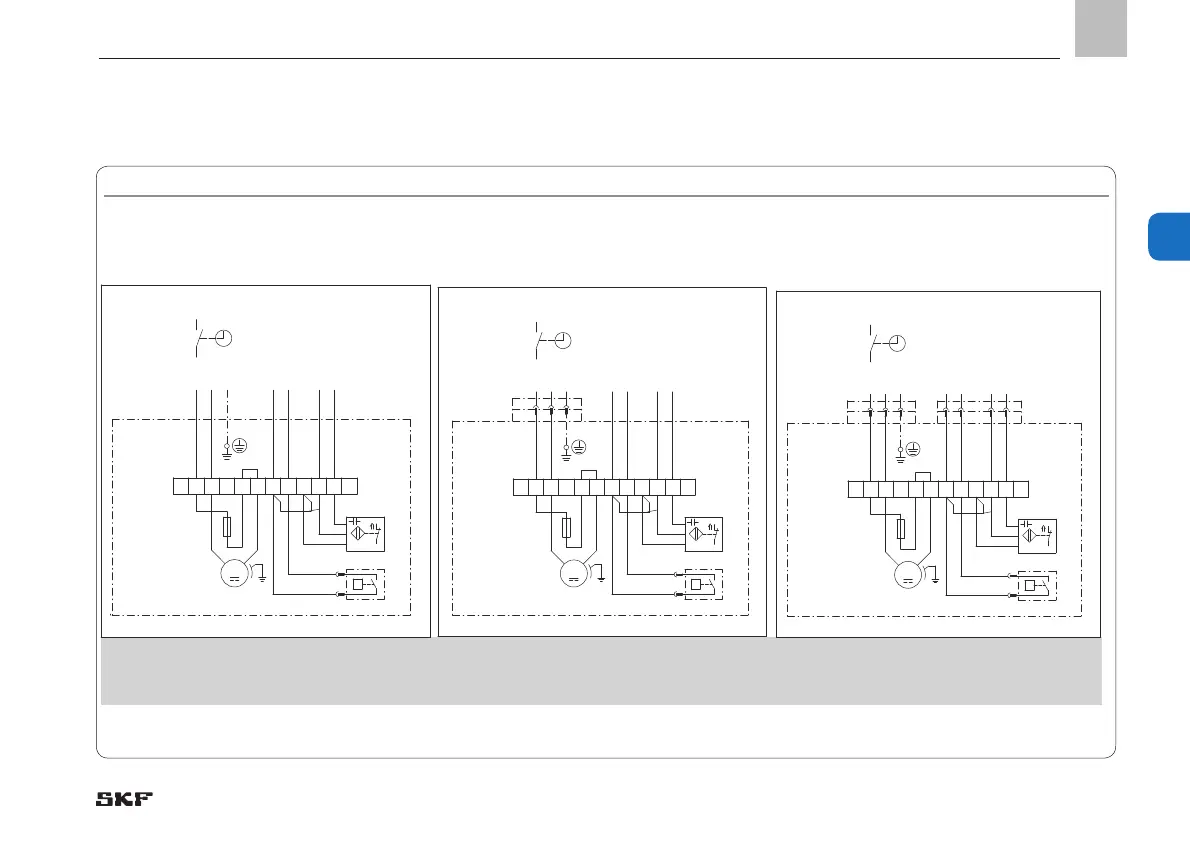
4.7.7 MKF, 2-liter reservoir, voltage design 24 V DC, without pushbutton
MKF, 2-liter reservoir, voltage design 24 VDC, without pushbutton, Fig. 17
Connections via:
1) Optional See Chapter 4.6.1 for legend to the terminal diagrams
2x cable glands
1x XS1 connector (DIN EN 175301-803 A)
1x cable gland
XS1 connector (DIN EN 175301-803 A)
XS2 plug (M12x1)
MKF1-11A _ _ 2000+924MKF1-11A _ _ 1000+924
MKF1-11A _ _ 4000+924
MKF1-11A _ _ 0000+924
MKF1-11A _ _ 3000+924
1 32 4 5 6
P
GY
GY
87 9 1210 11
1)
RD
BK
1)
M
L+/S
PE
24V DC
+24V DC PELV
DS Signal
WS Signal
GNYE
L+
BN
BK
PNP
BU
0V DC (M)
951-115-031
DS
X1
M
WS
F
1 32 4 5 6
P
GY
GY
87 9 1210 11
1)
RD
BK
1)
M
L+/S
PE
1 2 PE
+24V DC PELV
DS Signal
WS Signal
BU
BK
GNYE
24V DC
L+
BN
BK
PNP
BU
0V DC (M)
951-115-032
DS
X1
M
XS1
WS
F
1 32 4 5 6
P
GY
GY
87 9 1210 11
1)
RD
BK
1)
M
L+/S
PE
1 2
BU
BK
PE
+24V DC PELV
DS Signal
WS Signal
1 4 2
BN
BK
WH
3
BU
GNYE
24V DC
L+
BN
BK
PNP
BU
0V DC (M)
951-115-033
DS
X1
M
XS1
XS2
WS
F
EN
4. Assembly
 Loading...


