58
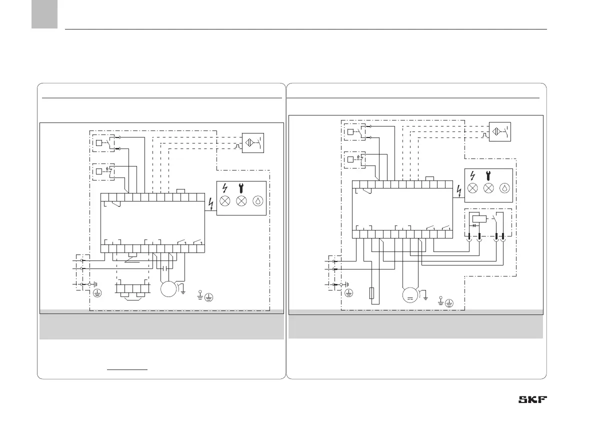
4.8.2 MKU, IGZ36 control unit, voltage design 230/115 VAC
MKU, IGZ36 control unit, voltage design 230/115 VAC, Fig. 28
Connections via:
1) Machine contact MK is only required in counter mode (operating mode D)
2) The control unit can be switched between 230V and 115V AC.
The pump motor is not switchable!
See Chapter 4.6.1 for legend to the terminal diagram
1x XS1 connector (DIN EN 175301-803 A)
1x cable gland
X1:16 = Fault
X1:14 = Normal operation
MKU2/5-12/3/4E _ _ 1000+428/+429
l4 + l5l3l2 +l1+
d
2
IGZ36-20-S6-I+471
L
1 1
B B
2 N
dC
1 3
d
- -
M
C
X1
X1
MK
1
B B
2
XS1
Display
WS
DS
+
-
1 132 3 4 5 6 7 8 9 10 1112
14 15 16 17 18 19 20 21 22 23 24 25 26
BU
BK
BN
1~
1)
3 4 5 6
12PE
115V
230V
2)
BK
BU
230V/115V 50/60Hz
L1
PE
N
2)
BK
GY
BK
GY
SL1 SL2
DK
Q
P
PNP
BN
BU
BK
951-115-087
4.8.3 MKU, IGZ36 control unit, voltage design 24 VDC
MKU, IGZ36 control unit, voltage design DC, Fig. 29
Connections via:
1) Machine contact MK is only required in counter mode (operating mode D)
See Chapter 4.6.1 for legend to the terminal diagram
1x XS1 connector (DIN EN 175301-803 A)
1x cable gland
X1:16 = Fault
X1:14 = Normal operation
l4
+
l5l3l2
+
l1
+
d
2
IGZ36-20-S6-I+472
L
1 1
B B
2
N
dC
1 3
d
- -
X1
X1
WS
DS
K1
Display
MK
+
-
XS1
F
1 132 3 4 5 6 7 8 9 10 1112
14 15 16 17 18 19 20 2122 23 24 25 26
BK
BU
BK
GY
BK
GY
Q
P
86
85
30
87
SL1 SL2
DK
BK
RD
BK
BU
BK
1)
PNP
MKU2/5-12/3/4E _ _ 1000+924
12PE
24V DC
L+
PE
M
M
BN
BU
BK
951-115-089
BN
RD
EN
4. Assembly
 Loading...


