Section 06 REAR SUSPENSION
Sub-Section 02 (SC-10 SUSPENSIONS (ALL VERSIONS))
06-02-16
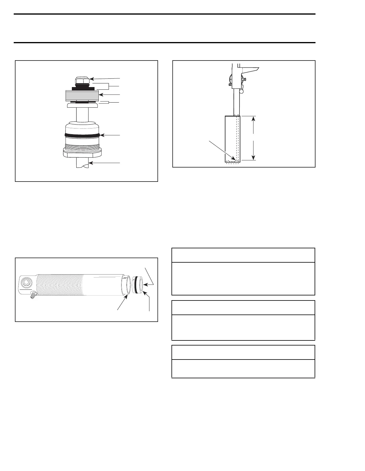
1. Damper nut torqued to 11-13 N•m (96-108 lbf•in)
2. Rebound shim pack
3. Piston
4. Compression shim pack
5. O-ring visual inspection seal carrier assembly
6. Damper rod
Reinstall floating piston into damper body. Use
molybdenum disulfide grease (example: molykote
GN paste (P/N 413 7037 00) to ease O-ring past
damper body threads with floating piston guide
(P/N 529 0266 00).
1. Push (slowly) by hand
2. Hollow side of floating piston must face rod side
NOTE:
Lubricate inside of piston guide with
molykote GN paste (P/N 413 7037 00).
1. Top of the piston
A. Required distance
Install floating piston to depth of 151 mm (5.94 in)
for front damper, 190 mm (7.48 in) for rear damp-
er and 141 mm (5.55 in) for center damper. Mea-
sure from the top edge of the damper body.
NOTE:
If the floating piston is installed too
far into the damper body, light air pressure
through Schrader valve (with core removed) will
move piston outward.
Replace shock oil with Bombardier HPG shock oil,
(P/N 413 7094 00), to approximately 10 mm (.393
in), from the base of seal carrier threads.
A06F2DA
1
2
3
4
5
6
A06F14B
1
529 0266 00
2
◆
WARNING
Whenever using compressed air exercise
extreme caution, cover damper opening
with shop cloth to reduce chance of possible
injury.
-
CAUTION
Moisture laden compressed air will contami-
nate the gas chamber and rust floating pis-
ton.
◆
WARNING
Always wear protective eye wear whenever
using compressed air.
A27F07A
1
A
'
 Loading...
