Section 03 ENGINE
Sub-Section 02 (599, 699 AND 809 ENGINE TYPES)
03-02-10
NOTE:
Engine must be removed from chassis to
perform the following procedures.
CLEANING
Discard all oil seals, gaskets, O-rings and sealing
rings.
Clean all metal components in a non-ferrous met-
al cleaner. Use gasket remover (P/N 413 7085 00)
accordingly.
Remove old paste gasket from crankcase mating
surfaces with Bombardier gasket remover (P/N
413 7085 00).
DISASSEMBLY
General
To remove drive pulley, refer to DRIVE PULLEY
04-03.
To remove magneto, refer to CDI MAGNETO 03-04.
2,3, Crankshaft Bearing
To remove bearings from crankshaft, use a pro-
tective cap and special puller, as illustrated.
1. PTO side
2. MAG side
INSPECTION
NOTE:
Refer to LEAK TEST AND ENGINE DI-
MENSIONS MEASUREMENT 03-03.
1, Reed Valve
With blade stopper removed, check reed valve for
proper tightness. There must be no play between
blade and valve body when exerting a finger pres-
sure on blade at blade stopper location.
In case of a play, turn blade up side down and re-
check. If there is still a play, replace blade and/or
valve body.
1. No play
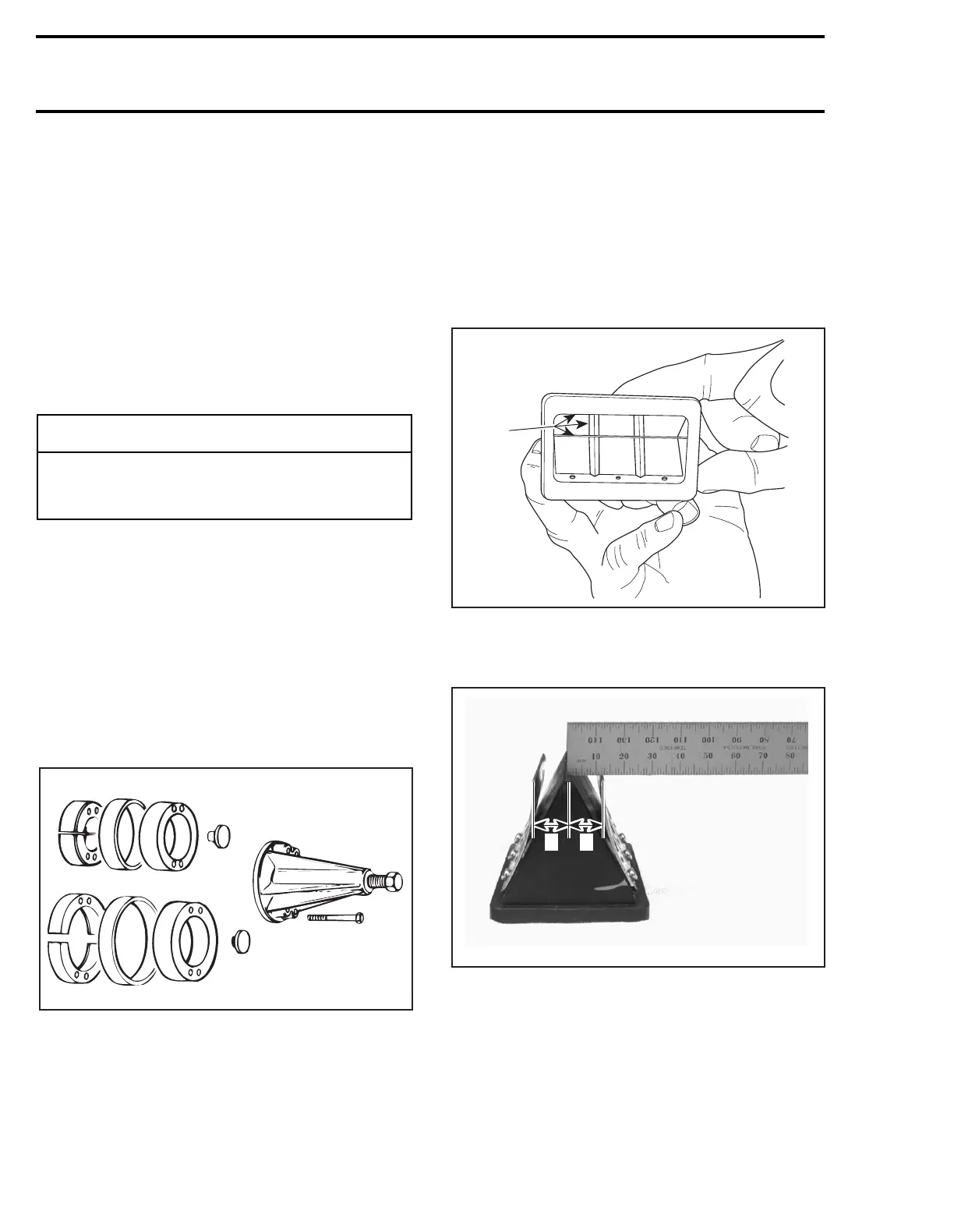
Check blade stopper distance from center of reed
valve block.
TYPICAL
A. 599 Engine: 14 ± 0.25 mm (.551 ± .010 in)
699 Engine: 12 ± 0.25 mm (.472 ± .010 in)
809 Engine: 12 ± 0.25 mm (.472 ± .010 in)
Bent blade stopper as required to obtain the prop-
er distance.
-
CAUTION
Never use a sharp object to scrape away old
sealant as score marks incurred are detri-
mental to crankcase sealing.
A00C0HA
1
2
A06C0FA
1
A06C36A
A A