Page 88 (Model J)
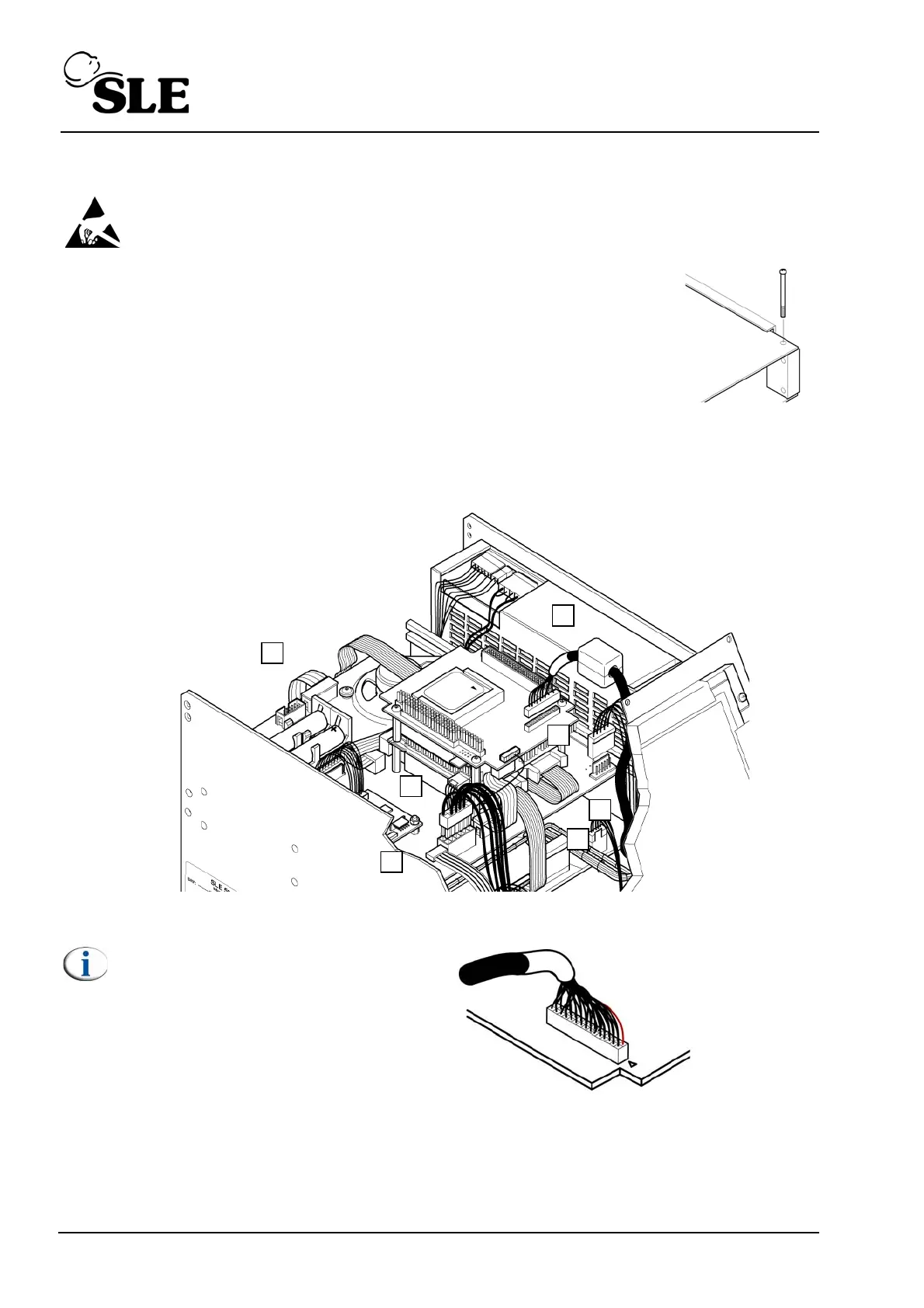
16.4.1 L0275/OEM2 Computer/Display Control assembly
Warning: The Computer/Display Control assemblies are static sensitive
devices.
1. Remove the PCB locking screw. This will allow the top board assembly
to slide forward a small amount which gives better access to the edge
connectors of the top board.
2. Disconnect the display cable connector (A).
3. Disconnect the touch screen connector cable connector (B).
4. Disconnect the carrier board power cable connector (C).
5. Disconnect the inverter board power cable connector (D).
6. Disconnect the CAN card interface cables (E & F).
7. Disconnect the RS232 connector cable (G).
8. The carrier board can now be removed by sliding towards the rear of the ventilator.
Note: The orientation of the
display cable .
Red/Black wire
Pin 1
L0275/OEM2