89
Scope Multimeter Getting Started
Channel 3 Lead
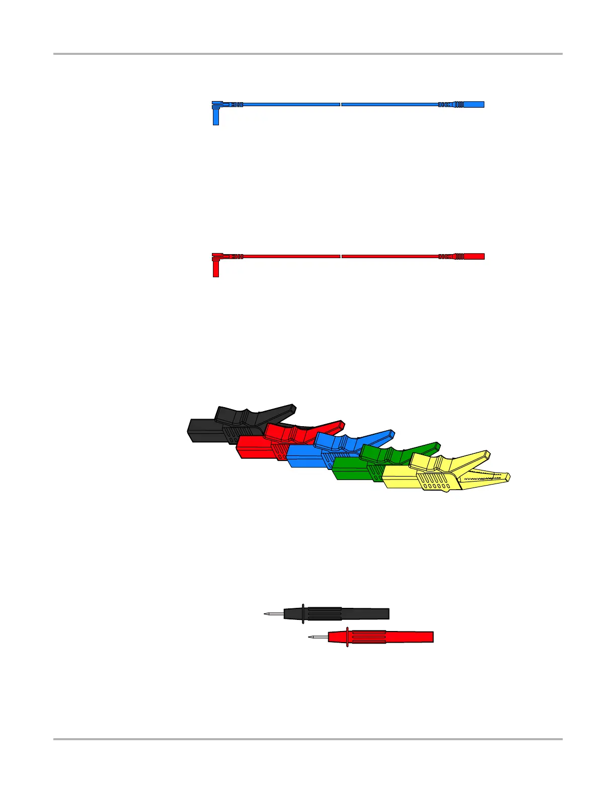
Figure 8-3 Blue Channel 3 lead
The non-shielded blue lead (Figure 8-3) is used for either Channel 3 or Digital Meter minus (–).
The lead color matches the color of socket 3 on the diagnostic tool, as well as the color of trace 3
on the test screen.
Channel 4 Lead
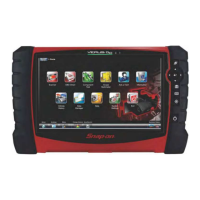
Figure 8-4 Red Channel 4 lead
The non-shielded red lead (Figure 8-4) is used for either Channel 4 or Digital Meter plus (+). The
lead color matches the color of socket 4 on the diagnostic tool, as well as the color of trace 4 on
the test screen.
Alligator Clips
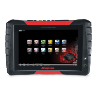
Figure 8-5 Alligator clip
Four insulated alligator clips are included and colored to match each test lead, a black clip for the
common ground lead is also supplied (Figure 8-5). Each clip plugs into the straight end of a
channel lead.
Test Probes
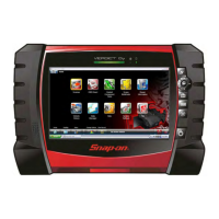
Figure 8-6 Test probe
Two test probes are included, one black and one red (Figure 8-6) and plug into the straight end of
the test leads.